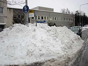
Last weekend we had a severe snow blizzard, so I didn't venture out much - the bus stop and pedestrian walkway (note signs!) just outside my house looked like this when the snowplows had done their job.
(Fortunately, my car is in a rented garage - many of my neighbors now have igloos instead of cars...)
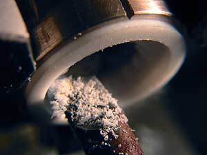
So, I had plenty of time to spend in the workshop, producing my own white fluff - of PTFE, i.e. Teflon. Fortunately this is an easy material to turn - with a sharp tool, you can easily shave off a thou or even less. This is not possible with many other plastics, such as Nylon. Note how how the piece is held in the chuck in a split piece of tubing. Putting a thin PTFE ring straight in the three jaw would distort it severely.
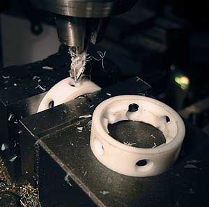
I made piston valve rings of my own design - instead of making two separate rings, I made one, but perforated, so that the PTFE can expand without causing problems.
Since I don't have inside/outside micrometers for this size, I tested my machining of the rings by matching them to their tubes: At room temperature, they are an easy sliding fit, but cooled in cold tap water (i.e. less than 10° C), they drop through by their own weight, but heated in hot tap water (55° C) they need a slight finger push to slide through the valve tube. This means that they'll give a steam tight but still easily sliding fit at working temperature, i.e. around 120-160° C...
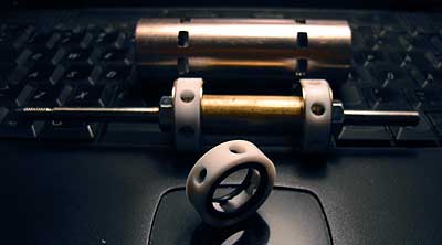
That is important, since Teflon has a temperature expansion coefficient six times that of brass or copper, and I must not make the rings too tight. In fact, since the ring diameter will expand by about 0.3 mm from 20° to 140° C (that is as much as 12 thou, really!), resilience, and sealing, is provided by two O-rings inside the PTFE ring, as seen here. The valve ring actually never touches the valve stem metal, instead it "floats" on the O-rings!
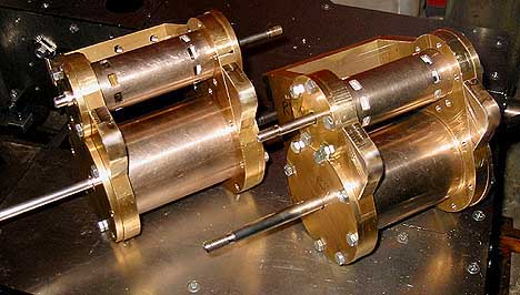
Two cylinder groups test assembled. You can see the Teflon valves in the liner openings...
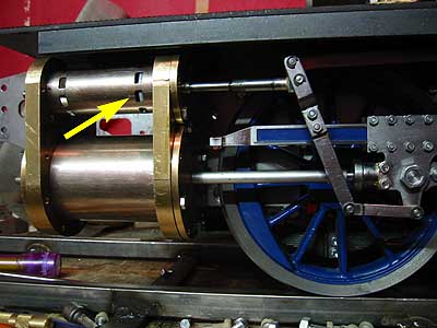
... and I could try the valves on the loco and check that the dimensions were correct - by rolling the loco I could ascertain the valve opened and closed as it should, with proper lap and lead. The valve crosshead and all cover glands are still "vaporware", but I'll decide how to build them, shortly...
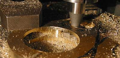
Next step is making the steam channels between valve liner and cylinder ends. An ovoid "collar" made of 10mm thick brass, and some milling with a suitable Woodruff cutter provided the necessary form. Finicky work!
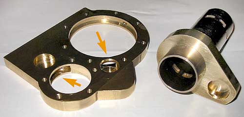
Here is a cylinder end plate, where the steam passages are clearly seen (arrows), and a valve liner with its collar. Note how the collar totally encircles the ports in the liner.
Next, when I have made the still missing parts (some short connecting tubular pieces) comes the final assembly and silver soldering. The small hole in the collar will mate with its counterpart in the end plate.
As Guv' Arnold used to say: "I'll be back!"