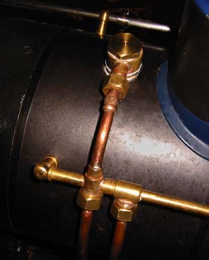
I finally made proper clack and bypass valves... The fitting on the handrail end is the feed bypass, which is controlled from the cab. The connection on top of the boiler contains a somewhat unconventional clack valve, which protrudes into the boiler...
... this drawing shows how I did it. The valve itself is a typical simple ball valve, but I made a double-threaded fitting that screws into the boiler's bushing. With this construction, an unsightly, high (or long, if horizontal) clack on the outside is avoided. This design added only 3 mm (0.1") height to the "banjo" union, which I'd have to have there anyway...
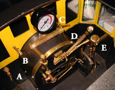
This shows all the fittings inside the cab (whistles and their valves still missing):
A is a water gauge for the side tanks, B shows the bypass control lever, C is the control for the cylinder drain cocks, D is a new throttle handle, with a ratchet which prevents it from moving or opening by itself, and finally E shows the steam brake valve and the tiny brake pressure gauge (from a fire extinguisher - see this page). The reverser lever is hidden behind the throttle handle in this photo.
NOTE: I will change the upper connection to the water glass. The manifold (or turret) has connections to other equipment (brakes, pressure gauge, whistle), and the water level jumps up in the glass whenever steam is used. This is NOT a good practice. In my case, the whistle gets water in the steam! If there would be a blower or any other equipment using steam on a constant basis, the gauge glass would erroneously show too high a level instead of just a jump up and down - and this is outright dangerous! (Thanks, Ross Forsyth, for your comments regarding this!)
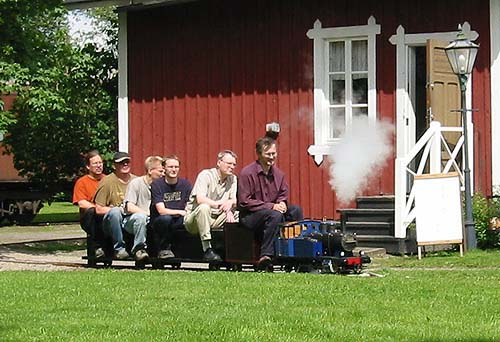
Today I did a "dress rehearsal" at the Hyvinge RR Museum's track, since I've promised to run for the public next weekend when they have their annual "Tractor day"...
During testing, the loco pulled this load (approx. 900 lbs of passengers) with no problems, but on the 3.5 % upgrade, situated on a curve, I had to have a steam pressure of at least 4 bars (56 psi) in order to manage, with a lower pressure I risked stalling. On the other hand, I could reverse up the 8 % hill, (which is on a straight, and is normally run only down the incline...), with two hefty adult passengers, without slipping - that is something I would never have believed!! The fact that 100% of the loco is tractive weight sure helps!
Here's a diagram of propane consumption (454 g = 1 lb) related to orifice sizes (1 mm = 40 thou).
Working hard, my loco uses 1.5 kg (3.3 lbs) of propane per hour, since the two burners have 0.6 mm orifices - this gives a maximum burner power of some 20 kW - of which I can get out perhaps 1 kW (1.3 hp) as mechanical energy for short periods only, or maybe 0.3 kW (less than 0.5 hp) continuously, estimating a total efficiency of only a little over 1%. (I'd like to have a dynamometer car available... ;-)
Idling, with the burner pressure at 40 kPa (5 psi) - which is the lower limit before the flames start fluttering - the gas consumption is one fifth of full power, i.e 300 g (11 oz) per hour, and still the safety pops every few minutes - that 4 kW has to go somewhere...