I don't know if I was brave or stupid, but I decided to pressure test the new boiler immediately, without installing any flue supporting rings. (I've contemplated that, but press fitted on the INSIDE of the 0.060 walled tubes - they would double as holders of the burner's wire mesh cone.)
The flues are thoroughly annealed for about a quarter of their length in each end - they were glowing red for a distance of 150 mm (6") while I was silver soldering the 5mm thick tubeplates to the 3mm thick boiler shell. Furthermore, differential thermal expansion had made the flue tubes curve slightly - however, they had NOT gone out of round, rather they were curved longitudinally, about 2 mm (3/32") over the entire 600mm (24") length...
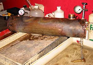
... So, with trepidation, after having plugged up the 8 holes in the
boiler with various plugs and fixtures, plus three manometers, one of them calibrated to 2%, I started pumping... The picture shows the setup, boiler is placed over photo developing trays, the hand pump is submerged in water. There is a ball valve (red handle) between the pump and the boiler - this ensured that an accidentally leaking pump would not upset the test!
I had surmised the following: since I had carefully let all the air out of the boiler when filling it with water, there would be no pressure reserve in case of a flue collapse - which would thus not proceed suddenly. And, since I was pumping manually, with a pump having a stroke of only 3 cu. cm (0.2 cu. in), I would have a feel for any impending catastrophe - pumping resistance suddenly decreasing, for instance...
Well, after pumping a few strokes to get the pressure to creep over the zero mark on the manometers, lo and behold - I needed only FIVE additional strokes to get the pressure up to 14 bars (200 psi). That's one cubic inch of water!
This volume was obviously needed to compress the residual air in the manometer bourdon tubes, and whatever tiny air bubbles that were still left in the boiler. When the pressure started rising, the rise was almost linear - 3 bars (45 psi) per stroke. The pumping resistance was increasing all the time, too.
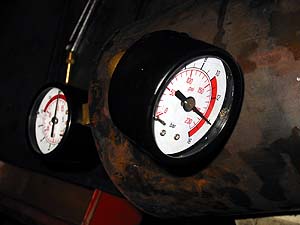
The manometer needles stayed at 14 bars for several minutes - thanks to PTFE tape, and the ball valve I had installed in the feed line! Alltogether, I had 14 screwed joins with PTFE packing... All three manometer showed the same pressure, the difference between them was less than 0.3 bar, 5 psi. This proved conclusively that the cheap ones (6 Euro or USD) worked as they should!
After one hour, the pressure had dropped less than 3 bars, standing at 11.5 bars - I attribute this to the few drops of water that had seeped through one of the packings. I think this proves that the silver soldering was successful - no leaks there.
And, biggest relief of all: the flues are still round! Am I lucky, or what?
Whew! :-)
Close this window when you are ready...
Any information presented on this website (especially any do-it-yourself instructions) is given without any acceptance of liability for damage or injury - so, always remember: SAFETY FIRST!
The material on this page and its related pages is Copyright © 2001-2007 by J-E Nystrom. You may NOT copy, transmit and/or publish any of my images or texts in print, electronically, on your own website or in any other way. The author retains all rights to this work, with this sole exception: Storing the pages on your own computer or printing out a paper copy, for your own, strictly personal use is allowed.
You may, however, freely link to the "Building Live Steam Locomotives" page at: http://www.saunalahti.fi/animato/steam, or to my Animation Home Page at: http://www.saunalahti.fi/animato. You should NOT link directly to THIS page, since it's address may change in the future. Also, you may not put any of these pages or pictures into "frames" on your own website.
Thank you.