First, the back! Here, I've just used a threaded rod to keep the casting in place on the face plate - but note the three pieces of plywood (brown) under the rim; these prevent the counterweight and axle boss to contact the face plate. This insures that the casting is registered from the front of the tire.
With the back side turned flat, it was easy to attach the casting to the face plate with three bolts & washers. I centered the casting using the inside edge of the rim as my reference. Now I could turn the tread, the counterweight and boss.
At the same setting, I bored the axle hole to size - the original hole was just for attaching the casting in the previous operation, and was not properly centered. Boring, instead of drilling, ensures that the wheel will run true.
After I've mounted all the wheels on their axles (I plan to use Loctite, plus a securing pin), I'll skim just a shaving off the treads - in case of any slight error in assembly.
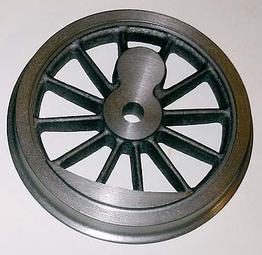
Mounting the almost finished wheel on a mandrel (made from a Morse 2 chuck arbor, which is soft enough to be easily turned to size), I finally turned the flange concentric with the rest. Now the castings started to look like wheels!
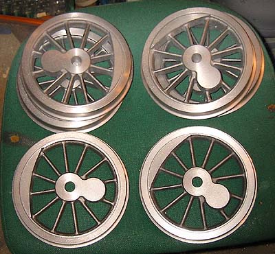
The six wheels ready for the next operation, the holes for the crank pins.
To get them at precisely the same distance from the axle in all the six wheels, I put the mandrel I had made into the M2 bore of my little rotary table. Now I only needed to center the mandrel under the mill chuck - this was accomplished with the help of a center drill of the same size as was used when the arbor was manufactured. Then, all I had to do was to move the mill table the correct distance (half the piston stroke), and lock everything in place.
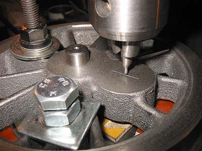
I had marked the center line of the boss on each wheel, and used the rotary table to visually get the line under the center drill - no high precision needed, since a small error here doesn't affect the distance to the axle! (Note that I've put a few pieces of plywood under the wheel - to get clearance for the drill, so as not to foul the surface of the rotary table...
After drilling with successively larger drills, I removed the wheel and reamed the hole to the exact size by hand - easy, since the last drill used was only 0.1 mm undersize.
This method ensured that all crank pin holes are in the right place.
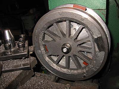
Two of the wheels of this 0-6-0 have larger counterweights - and I only made one pattern for the castings...
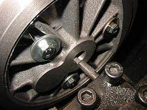
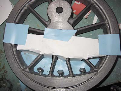
Well, to correct that, I first drilled & tapped holes between the spokes for three "securing bolts".
Then I made a rough little "mold" of paper and plastic tape, and...
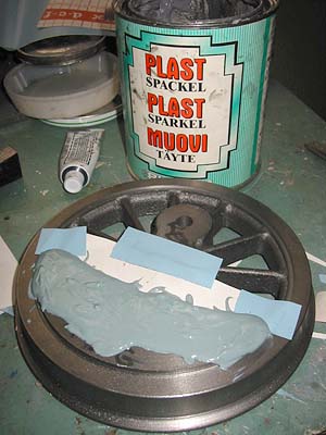
... filled it with polystyrene filler! The bolts, now entirely inside the counterweight, ensure that the chunk of filler stays put!
When the filler had hardened, I could mill and file the new, larger counterweights to size.
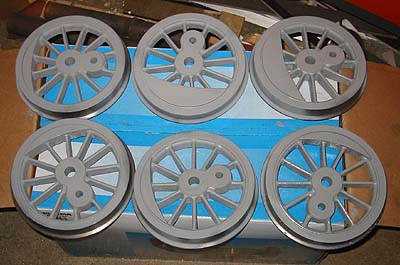
All six wheels are finally spray painted with primer - this makes them much more pleasant to handle, since less black graphite gets on my hands!