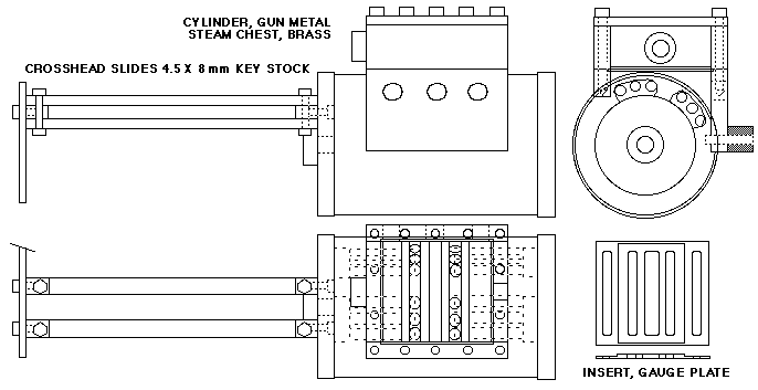
Fabrication of the cylinders
I adapted the original drawing (where the cylinders were of cast iron) to one suitable for cylinders fabricated in parts. Note how the steam channels to the cylinder ends will be drilled through the thick body of the cylinders - if I had made them of cast iron, several mold core pieces would have been needed to get the channels into the castings - that's why I decided to use the fabrication method instead...
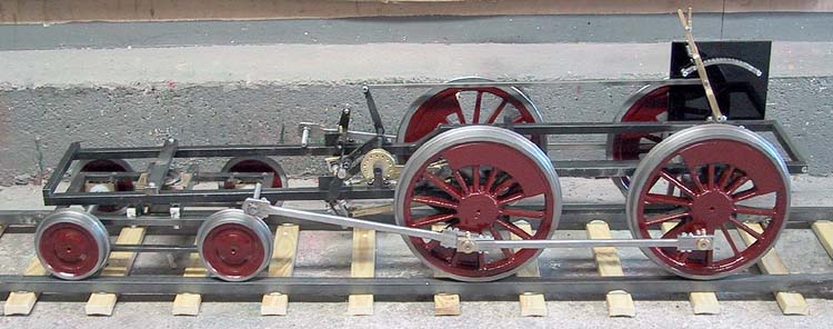
Piston & crosshead, 2001-07-22
In this shot, the piston is about 5mm from "dead" position - the recessed cylinder cover will be only 3 mm from the piston at minimum. Of course, there is a recess in the cover to allow space for the piston nut.
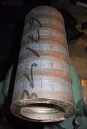 Starting with a 4 kilogram (9 pound) chunk of extruded 85-5-5-5 bronze, also called gun metal...
 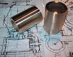 ... I turned the two cylinders to the right outer diameter.
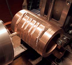 Using the home-made milling vise attachment described earlier, I used my lathe to mill the recesses for the steam chest. Note how I've clamped the cylinder between two pieces of rectangular steel, one of which is held by the vise.
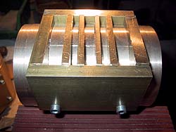 The walls of the steam chest are 8 mm thick, and will be tapped for the bolts that will hold the upper part of the chest and its cover in place. There are 4 thinner, separating walls fitted within the chest. I made them about 1 mm higher than the outer walls, to allow for subsequent machining. In addition to dividing the chest into chambers, they will also support the thin steel plate steam-port insert. All brass parts will be silver soldered together to form a steam-tight enclosure. The top surface of the steam chest will be milled flat, and I will use gasket paste to seal the seams between the chest and the insert.
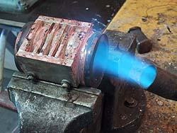 Silver soldering the whole chunk - it took quite a while to get all that mass to red heat...
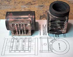 The two cylinders are ready for machining! But how to get an absolutely plane and true surface to the steam chest without a proper mill? I don't trust my homemade milling attachment with any job of this importance ...
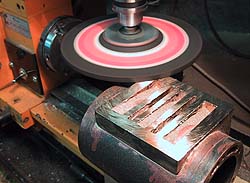 Grinding to the rescue! Using a 6 mm thick angle grinder stone, I was able to use my small lathe (size of a sewing machine, but with a milling attachment) to plane the surface very nicely, to within a couple of hundredth mm (a thou or so)... This small milling attachment would not have been rigid enough for actual milling, but for grinding, and with a small feed, it worked perfectly! To get an even better finish, I used some fine grit abrasive paper placed on a piece of sheet glass - and ground the steam chest with a few back-and-forth strokes on this absolutely plane grinding surface.
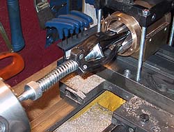 Having bored the cylinders to the correct size, honing was the next step - I bought a cheap (approx USD 15) honing attachment intended for a handheld drill, modified it somewhat, and used the lathe for the honing! To get the exact placement of the cylinder, centered, straight and true, I first attached it to the 3-jaw, and then selected suitable packing material to fasten it to the cross slide (the flat steam chest surface downwards) using the home-made angle bracket as a clamp (partly seen in top right of picture). Then I could loosen the chuck's grip, and move the cylinder to the honing position, knowing that the bore now was aligned to the lathe's axis. I used light oil on the three honing stones, and ran the cylinder back and forth to ensure a smooth finish to the bore.
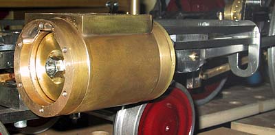 The left cylinder with piston, front end. Piston is of brass, rod is stainless steel, as are the nuts, piston and gland rings are Viton. Corrosion resistant, all! Note the steam passages in the top of the cylinder, should be large enough...
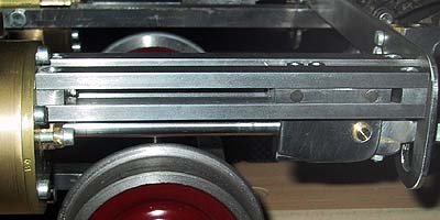 The crosshead is still a bit unfinished, needs to be formed at the lower edge. Slides and crosshead are made of - what else - key stock! Being high-carbon steel, there should be no friction problem - oil cups are yet to be added, naturally! The Allen head cylinder cover screws are not exactly prototype, but they will be hidden behind "cosmetic" brass covers like the ones on the original 3003.
Close this window when you are ready...
Any information presented on this website (especially any do-it-yourself instructions) is given without any acceptance of liability for damage or injury - so, always remember: SAFETY FIRST!
The material on this page and its related pages is Copyright © 2001-2007 by J-E Nystrom. You may NOT copy, transmit and/or publish any of my images or texts in print, electronically, on your own website or in any other way. The author retains all rights to this work, with this sole exception: Storing the pages on your own computer or printing out a paper copy, for your own, strictly personal use is allowed.
You may, however, freely link to the "Building Live Steam Locomotives" page at: http://www.saunalahti.fi/animato/steam, or to my Animation Home Page at: http://www.saunalahti.fi/animato. You should NOT link directly to THIS page, since it's address may change in the future. Also, you may not put any of these pages or pictures into "frames" on your own website.
Thank you.