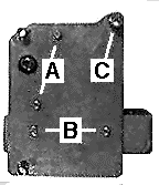
 So, let's start: This picture shows the back of the finished
motor. You can see the motor's attaching bolts (A), the bolts (B) holding
the switch box. and the three holes for camera attachment: one shown at
C, the others bottom and top left. Below this last hole you can see the
motor axle. How do you know where to drill these holes? Put a piece of
transparent paper on the side of your Bolex, and mark the three (M 3.5 threaded)
holes in the camera body: to the right of the winding crank (remove it
first by turning it clockwise); above the 1:1 axle; and in the lower right
corner. These holes may have factory-installed "cosmetic" screws.
They can be safely removed. Also, mark the center of the 1:1 axle on the
paper. This will be the position for the motor axle. Note:
these positions are critical, so mark them carefully, to within 1/4 of
a millimeter.
Now, it's easy to transfer these
markings to the brass sheet to make the motor's base plate. Drill 4 mm
holes for the attachment screws, and a 15 mm hole for the motor axle. The
positions and sizes of the holes for the motor and switch box depend on
the size of the motor and box. You're on your own there...
As you can see, I have cut away part the upper edge of the brass plate. This makes it easier to see and reset the camera's frame counter which otherwise would be hidden behind the plate.
Next, make and attach three spacers to the base plate, to keep it at a suitable distance from the camera body, with all its protruding dials and levers: Cut three pieces of the brass (or copper) tube, exactly the same length, 7mm. (Use a file to ensure the ends are parallell, and all three are equal in length). Use a butane pencil torch, or a sturdy soldering iron, and solder the tube pieces to the base, so that they coincide with the three attachment holes (C). If you feel uneasy about doing this, you can leave the spacers loose, but attaching the motor then becomes a little cumbersome.
Test that the base plate with spacers
fits well on the camera. Three machine screws, M 3.5 x 10mm, are used to
secure it. It is important to use exactly this type of screws. The threads
in the Bolex are metric, and if you use longer screws, you may damage the
innards of the camera.
 Now, the most difficult part of the job: making the axle. In addition to connecting the motor to the 1:1
axle of the camera, it enables the motor to stop with the shutter closed
- an utter necessity!
First, drill a hole in one end of the brass rod, diameter 4.2 or 4.5 mm (these are standard metric drill bit sizes - in inches, you'd need an 11/64ths drill).
In the other end, drill a hole that fits your motor's gear box axle diameter. There should be a tight fit! Both holes should be around 10 mm deep.
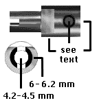
Next, you must reduce the diameter of the end with the 4.2 (or 4.5 mm) hole to between 6.2 and 6 mm (as close as you can get, this is a critical dimesion). If you don't have access to a lathe (most people don't), then you can still make the axle by inserting the brass rod piece into the chuck of an ordinary electric drill, and use a file to trim away the excess metal while the drill is rotating. INJURY RISK ! Be careful! The drill rotates at high speed, and metal filings fly around. Use safety goggles!!! The drill MUST be attached to a sturdy stand when you do this! (Of course, you CAN file the rod just by hand, but it takes longer, and it's much harder to get round!)
Next, use a metal saw to make the narrow end into a "fork" that will engage the pin in the camera's 1:1 axle. Saw to a depth of 4 mm. See the illustration above. Test the result by fitting the fork on the 1:1 axle. There should be a LOOSE fit!
Now, use a file to make a flat
indentation on the wider part of the rod, adjacent to the narrowed part,
see picture again. This indentation will engage the microswitch and stop
the motor with camera shutter closed. It should be a little wider than
the roller on your microswitch, and should go down to the 6 mm part of
the rod. Again, see the illustration. Also, drill a hole in the motor end
of the rod. This should be threaded to accept a tightening screw (3 to
4 mm dia.), or, if you don't have the tools to make threads, drill all
the way through. Then you'll have to drill a corresponding hole through
your motor's axle, too, and attach the rod to the axle with a cotter pin.
The important thing is to get a tight fit, well centered, so that the "fork"
end of the axle doesn't wiggle as it rotates.
 When you have the axle attached
to the motor, you can try out the position and plan how to attach the motor
to the base plate. I cannot give exact instructions, because your motor
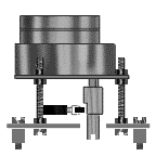
may be different from mine - mounting holes in different places, or more than just the two my motor had. I have used two long machine screws, secured
to the base plate with nuts. Additional nuts keep the motor attached, see illustration.
In this way, you can adjust the
height of the motor exactly, by moving the nuts. You can also see the spacers
below the base plate, and the microswitch, its roller touching the indented
axle. The best way to attach the switch to the base plate is with a small
piece of brass, drilled to accept screws to hold the switch, and bent so
that the switch is in a good position (see next page). For every turn,
the switch should click when the roller dips into the indentation.
For the final, electrical work, let's go to the NEXT Page