
Over the weekend, I drew up the boiler design for the 4-6-0. I've used the AMBSC (Australian Miniature Boiler Safety Committee) Code as base for my design, with a few changes, the most important being that I use Copper-Nickel, not copper, for almost all parts. Since this material - which is similat to Monel - has almost twice the UTS (ultimate tensile strength) of copper, I felt I could use a somewhat coarser spacing of the stays (which are larger in diameter instead). Here's the drawing (click on it for a larger version):
I'd like to hear your comments, thanks! 
Bill Boothroyd has been doing quite some thinking (thanks, Bill!) - he volunteered to design a transporter for the upcoming 4-6-0, tentatively numbered "999". Here are his thoughts, designs and drawings. We are all ears, any and all suggestions are welcome!
Transporter drawings
The following notes and referenced sketches relate to a concept for moving a relatively heavy (400 to 500 lbs.) model locomotive from in a small basement shop to an automobile for transport to a remote model railroad track.
The concept presented is for consideration HOWEVER any actual use of the ideas involved are totally at the users risk. These ideas are offered without any acceptance of liability for damage or injury - so, always remember: SAFETY FIRST! Moving anything heavy entails risk of injury or worse..
The Situation -- as I understand it:
The 999 locomotive is 55" long at the extremes and is 15.75" in width.
The estimated weight is in the 450 to 500 lb. range. The estimated center of gravity is between the front and middle driver and about at the wheel height ( 8.5" )
Shop Door width = 33 inches from frame to frame, the door interferes and reduces the free opening to 30". The threshold is 3/4" high. ( Note: the use of "handicap access hinges" would probably give another 2" of free opening.)
The thickness of the shop wall is 7" - outside the casing to outside the casing.
The hall width, wall to wall is 45" .
The hall steps have a rise of 10" in two steps and the step tread is 10" long.
The outside door is 36" wide and thus has 33" or so of free passage. It has a threshold height of 1/2" inside and 2" outside. There is 16" ( plus ) of hall between the edge of the top step and the outside door.
The pathway outside the basement door is paved and is relatively flat and wide.
Requirements and Desires ( Objectives ):
Transporting 999 to and from the car, may require two persons, but must not require significant lifting. Solo movement would be a plus.
The transporter must be as stable as practical with adding ballast in the transporter. A minimum 15 degree tilt in any direction is assumed as ISTR this was the minimum for standard commercial packages.
The lowest level needed is the automobile rear door threshold height.
The transporter is NOT intended to be used to load or unload at other locations.
999 transporter, in work bench mode should be 32 to 34 inches from the floor to the rail surface. Adjustable height would be a plus.
The transporter in work bench mode must not block access to any part of 999 other than the bottom. ( bottom access would be a plus. )
Vertical storage of 999 is NOT a requirement.
Accessory items like ramps for thresholds and bridges between the transporter and car are acceptable.
Now refer to the sketches: The sketches "Shop / Hall door" and "Transporter Footprint" show the door way between the shop and hall. The path of footprint points "X" and "Y" show a 'long swing' exit. ( The "X" swing is made - and causes the short "Y" swing. Then the long "Y" swing is made.
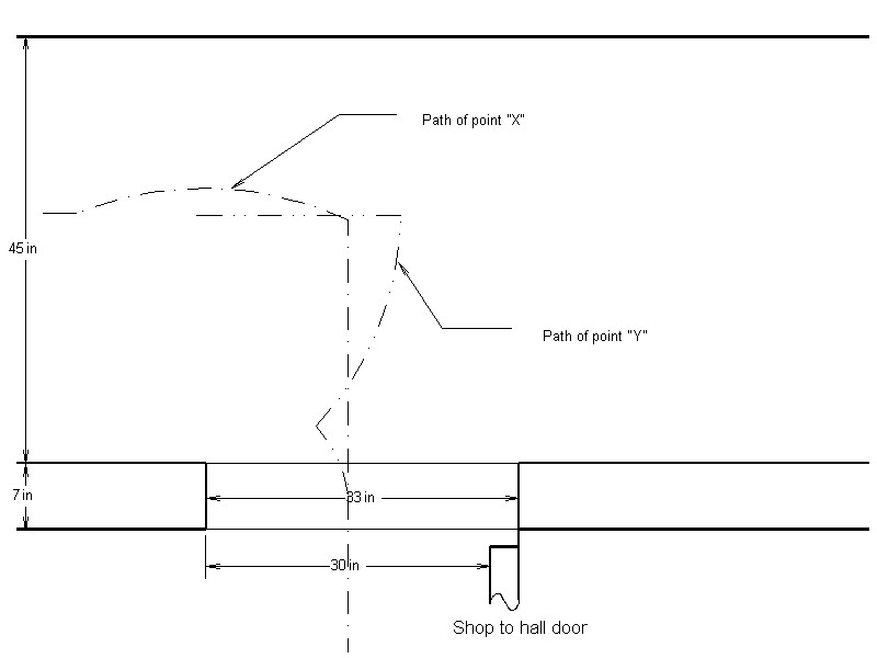

The 'narrow tail', 'wheels on wings' and the 'wasp waist' are needed to allow this relative easy exit. The wide 'nose' is important when the steps are reached.
The sketch, "Space Mission" Transporter Concept, gives a view of the system in transport mode.
![]()
For work bench mode, the use of a small hydraulic 'bottle jack' would allow blocks to be placed between the "Voyager" and the "Lander" - to lift the "Rover" to desired work height. In workbench mode, straps or bolts and wider feet should be fitted to give the most stable work bench. This system is a triple ( or quadruple ) layer arrangement. The bottom module, "VOYAGER" conveys the rest from in the shop to the hall stairs.
The next layer, "LANDER" rolls off and through the outside door, and to the car. There the third layer - The locomotive or "ROVER" rolls off and into the car.. Potentially, "LANDER" is made of a top and a bottom layer. The top layer may well serve as a bridge for off loading "ROVER" from the car.
No suggestion is made as to how to secure "ROVER" to the top of "LANDER".
The sketch, "Voyager", shows in more detail the bottom module:

A. The space under the 'nose' is such it just clears the hallway step allowing "VOYAGER" to dock tightly with the step..
B. The width of the 'nose' provides the path for the wheels on the "Lander" module.
C. The height of the 'nose' allows a ´" plywood bridge to be fitted that matches the height of the top of the exit door threshold.. Locating 'pins' are suggested to eliminate any tendency for a wheel on the "lander" to push the "Voyager" away from the steps.
D. The 'tail' is a jack point.
E. The cutout in the bottom of the 'nose' also provides a jack point.
F. Relatively small 'swivel casters' are shown ( and recommended ) as they minimize the amount of de-stabilization which occurs when swivel casters swivel. In as much as it is likely that force for turning will be applies to "Rover" ( ideally it should be applied as low as possible on "VOYAGER" ) and that swivel casters often pivot with a lurch, combine to make it desirable to have the worst case tilt point as far out from the center line as possible.
H. An alignment rail is shown to help align the "Lander" and the "Voyager" when "Rover" is being returned to the shop.
I. The roller tracks support the "Lander"during on and off loading. The back swivel casters on the "Lander" hang in mid air Up side down fixed casters are drawn, but many other designs would also work, possibly including use of UHMW plastic 'slick strips'..
J. A bit of detail is shown on the alignment pin idea. A similar idea is applicable to the Lander upper deck.
K. The top step 'bridge' is shown with 'side rails'.
The sketch of "lander" shows:

A. Bigger and wider wheels, fixed in front, and a "short offset" swivel caster on the back. Typical swivel casters have an offset approximately equal to the wheel radius where the short offset is more like 1". These steer harder, but do not cause near as much tip point shift when turning.
B. Cutouts nose and tail for jacking points.
C. Blocking points before the front wheels and behind the back wheels.
D. The deck height is lower than the rear floor of the present car.
D1. For maximizing stability of "lander" with "Rover" on board.
D2. Accommodation of potentially lower car or trailed deck height in the future.
In use, I see the "Lander" jacked up and blocks of appropriate height placed before the front and after the rear wheels to give maximum stability for the transition into the car. The car should also have a jack or blocks so there is no de-stabilizing change in the car position while "Rover" is moving in or out.
E. Not shown, but worth considering, would to make the top deck of "Lander" be detachable.
When bringing "LANDER" and "ROVER" back up a ramp ( 2" rise 24" run ) into the hallway outside door, I see use of a 2::1 block and tackle with the person being inside the building and "LANDER" and "ROVER" being pulled in. This reduces force needed and if the free end of the tackle is anchored to "VOYAGER" prevents anything from scooting apart. In addition the person can fine tune the transition of "LANDER" onto "VOYAGER".
The sketch "Thruster Option" shows an idea on how the process of moving from in the shop to into the hall could be made a 'solo' operation.

This shows two worm gear windshield wiper motors. One rotates an eccentric which forces a drive wheel into contact with the floor. The other motor rotates this drive wheel applying a force at 90 degrees to the "Voyager" long axis. The drive wheel and motor are show on a hinged bottom plate, which the eccentric swings.
This is anticipated to be an easy on - easy off item.
The sketch "SKYHOOK OPTION" show a modified "A Frame". It is anticipated that there would be two 2-spool winches which could be operated together or separate. It is also anticipated that this frame would be easy to assemble or disassemble.

As shown, the "Lander" top deck is being used as the platform for "rover". In this mode Rover can be placed close to ground level.
In a second mode ( not shown ) would have the cables located so as to be parallel in the long direction and located where, with suitable padding and packing, they could be wrapped around "Rover". Then, by operating the winches separately, "rover" could be rolled so as to access the bottom.
We are all ears, any and all suggestions are welcome!
Regards, Bill & J-E