First, construction drawings - these I make as I go, having finally found a good overall drawing (made in 1875) of the original locomotive. Here's my own drawing for the driving wheels.
This is the profile of the driving wheel pair, showing coupling pins, bearings and eccentrics. Axle diameter is 20 mm.
 Here are the other wheels needed for the loco; the bogie and tender wheels. Fortunately, these are rather simple patterns to make. I'll need to cast four of the former, eight of the latter.
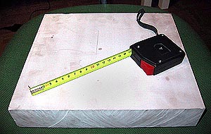 I started with a block of "synthetic wood" (brand name "Cibatool"), a plastic material that cuts just as easily as wood, but has no grain. This is an excellent material to work with. I sawed this 50mm thick block in half on a bandsaw, and cut out rough blanks for the three wheel patterns.
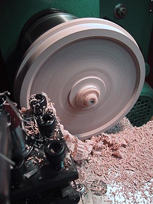 The 25mm thick block of the "synthetic wood" was first sawed to roughly
octagonal form, drilled in the center, put on a mandrel, faced, outside
turned to the proper diameter (always reckoning with the casting
shrinkage), turned over, then the outside (slightly sloping) profile of
the spokes, and the hub were turned. DUSTY WORK!
The 25mm thick block of the "synthetic wood" was first sawed to roughly
octagonal form, drilled in the center, put on a mandrel, faced, outside
turned to the proper diameter (always reckoning with the casting
shrinkage), turned over, then the outside (slightly sloping) profile of
the spokes, and the hub were turned. DUSTY WORK!
Now, some manual work: Mounting the piece on my smaller lathe - which has an overhead milling attachment - the mandrel held in a vise on the cross-slide. I could thus feed the piece in a straight line using the lathe's feed, and also BY HAND rotate the piece on the madrel - I had tightened the mandrel screw just enough so I could rotate the piece with some slight force. I had made a D-bit of the proper rounded and tapering profile, to get the proper form for the spokes:
You can probably visualize the process from the following, I regret I did not shoot any picture of the operation - it was a bit too fascinating, so I forgot the camera entirely... ;-)
I sank the special D-bit into the material close to the center (I had naturally carefully and clearly marked out the cuts to be made), advanced the leadscrew on the lathe to cut one side of the spoke, then I turned the piece manually, thus cutting kind of a figure "7" with a curved top - the top being the inner circumference of the wheel. Then, I lifted the bit, cranked the feed back to the starting point and turned the workpiece to the next mark, so the bit would sink into the right position when lowered again. Process repeated, with slight modifications for the holes adjacent to the counterweight and the connecting rod pin hub (where I didn't cut all the way through, but left a "bottom" to the hole, just as in the prototype). Then, having all the "7"-like cuts done, I cranked the cross-slide to the correct position for the final straight cuts, thus freeing a triangle of material between adjacent spokes.
The counterweight and the connecting rod pin hub I made separately, and glued them in place with hardening styrene filler. (In Finland, marketed as "Chemical Metal" by the Plastic Padding Co. - you probably have your own local brands of this gooey stuff...)
This entire process would NOT have been possible with a harder material,
or probably even with ordinary wood, due to the fibers which would have
deflected the piece in the manual freehand-cutting operation... That's
why I like this "synthetic wood"!
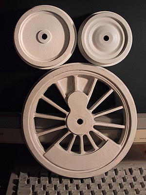 This "Mickey Mouse" picture shows the finished patterns for the wheels on the 3003 loco and its tender. Fortunately, all the drivers are identical, so I need only three wheel patterns for the whole locomotive! The driving wheel pattern is 210 mm (a tad over 8 1/4") in diameter, to allow for the shrinking in casting, and some machining - the final thread diameter will be 189 mm, flange 199 mm.
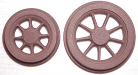
These are Tk3 wheel patterns that I did earelier - as mentioned elsewhere, my friend Kusti is making a type Tk3 engine model.