 But how shall I get the absolutely correct curve, and a smooth surface?
 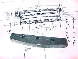 LINKS by GRINDING, HANGERS, ROCKERS etc.
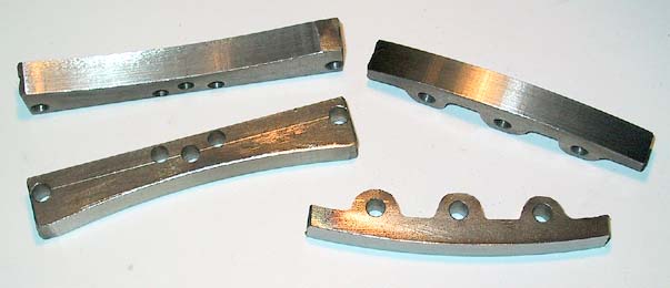
Again, key stock, 8x12 mm, will be the best raw material for the links. Here I have cut, drilled and roughly ground the curve for one part of a link - the prototype's links are made in parts, too, and not by machining out of the solid. Scribing the curve on the piece of steel enabled me to hand grind the radius to within a few tenths of a mm (a hundredth inch or two).
But how shall I get the absolutely correct curve, and a smooth surface?
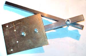
Taking an idea from a book, where the author milled his link with a special jig, I designed a similar apparatus - but without any feed mechanism needed for milling. The brass plate has holes for attaching the "raw" link pieces at the right radius from the pivot.
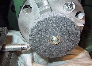 Mounting a small grinding wheel in the lathe chuck, I put a diamond in the toolpost, and trued up the wheel - this is VERY important! In fact, I did this before each one of the parts, just to be sure that any deformation due to wear would be minimal. Also note the rag covering & protecting the bed of the lathe. The truing up was really dusty...
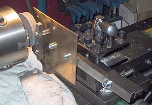 Here you can see the grinding in progress. The jig is fastened in the toolpost, straight & true. I used the cross slide to feed in the work about 0.05mm (about two thou) for each pass - this enabled me to comfortably move and hold the moving arm of the jig by hand - impossible had I been milling!.
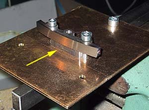 Here you can see the result, still attached to the jig - a shiny, true surface with the correct radius. A little emery will give an almost mirror-like surface. Note the spacer at the arrow (a piece of key stock), this was necessary to clear the hub screw of the grinding wheel.
The link parts so far, not yet filed & formed to perfection, but showing the nice sliding surfaces for the die block:
 Here's the drawing of the link, adapted to 1:8 scale...
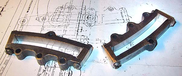
...and here are the finished links. Making these took quite a while, due to the intricate form. I still have to make the die blocks, link hangers etc. You can see some of the parts on the background in this picture, showing the 1875 drawing of the 3003.
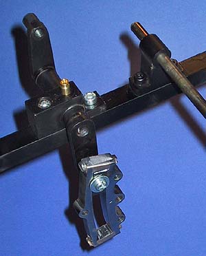 Well, a few days later and I had the rockers and their bearings attached to the frame - tentatively...
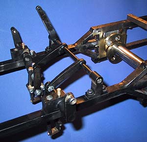 ... and in two more days, I had the lifting shaft done, with the arms silver soldered to the axle. The position in this picture shows full gear forward! I made the links & die blocks and the rocker bearings with the best precision I could, and there is indeed very little play - too much would offset the valve events...
 The parts marked in white on this small excerpt of the original drawing (see the entire drawing here) shows how far I've come - or, should I say, how much I yet have left to do!
Still to come: eccentric sheaves and rods...
Close this window when you are ready...
Any information presented on this website (especially any do-it-yourself instructions) is given without any acceptance of liability for damage or injury - so, always remember: SAFETY FIRST!
The material on this page and its related pages is Copyright © 2001-2007 by J-E Nystrom. You may NOT copy, transmit and/or publish any of my images or texts in print, electronically, on your own website or in any other way. The author retains all rights to this work, with this sole exception: Storing the pages on your own computer or printing out a paper copy, for your own, strictly personal use is allowed.
You may, however, freely link to the "Building Live Steam Locomotives" page at: http://www.saunalahti.fi/animato/steam, or to my Animation Home Page at: http://www.saunalahti.fi/animato. You should NOT link directly to THIS page, since it's address may change in the future. Also, you may not put any of these pages or pictures into "frames" on your own website.
Thank you.