_______________________________________________________________________________________
jDraft Manual
___________________________________________________________
SPARETIMELABS
for version 1.0.0.9b
jdraft@sparetimelabs.com
February 9, 2007
Contents
List of Tables
List of Figures
Chapter 1
Introduction
1.1 jDraft Application
jDraft is a simple 2D drawing program for creating engineering drawings. On a superficial level it
resembles simple drawing programs, such as old MacDraw or later day OpenOffice-Draw. But there is
a difference. Anyone who tries to draw accurate drawings (that would conform to good
engineering draftmanship guidelines) with these programs will soon find out that it simply is not
possible.
The main design goal of jDraft was to make it possible to draw geometrically accurate/correct
drawings in a simple and natural way, not unlike the time honored way of using a compass/divider and
a straight edge. jDraft is by no means the only show in town, plenty of 2D CAD software around.
Without badmouthing any particular software, I think it is fair to say that while those programs allow
the creation of accurate drawings, many of them are not that easy to use. s jDraft attempts to be an
animal of a different color, combining the ease of use of simple drawing programs with the accuracy of
full blown CAD applications.
1.2 About This Manual
It is perfectly possible to use jDraft without any manual at all. The user interface conforms to the
common idioms, concepts and practices of hundreds of other ’office’ applications. This manual is not
about describing every button and check box in every dialog and window in the software. Instead, this
manual tries to give insight into the design philosophy and advice at a higher level on how to use the
software, addressing the deeper, underlying concepts that are not obvious from the user
interface.
Unavoidably, this manual contains a bit (no pun intended) of computer jargon, some of which is
specific to the operating system the application is being used on. It is not necessary to understand this
jargon, it is included for the benefit of those who feel they need to / want to know it. You can safely
ignore it. In most cases, using the software is totally intuitive if you are the least bit of computer
savvy. In case you experience some ’computer’ woes you might want to lookup the jargon
bits.
1.3 Mac OS X Notes
Mac OS users should substitute the COMMAND (aka Apple) -key for the CTRL -key.
In Mac OS, the CTRL -key is used together with a mouse click to effect the Right -click of other
platforms.
1.4 Go on, Take Her for a Spin!
Reading about a thing is all very well, but there is nothing like the real thing. So why not, take her for
a spin!
Users of this application are most likely computer savvy enough to unpack it and just do
it.
Just double-click on the application icon and you open up a brand new but empty
drawing.
Select a line tool from the drawing tools palette and click or drag on the drawing area to create
some shapes. Click on the snap tools to experiment how the cursor snaps to shapes you’ve already
created, as you draw.
Go on, draw circles within circles (not a biblical reference here).
Pick the selection tool. Click and drag a shape to move it. Drag a box around the circles to select
them. Click the fill icon to create a hatched area.
1.5 Contacting SpareTimeLabs
To contact SpareTimeLabs email to address
jdraft@sparetimelabs.com.
All feedback and suggestions are welcome.
See, it’s easy!
Chapter 2
Installation
2.1 Hardware/Software/User requirements
2.1.1 User requirements
This manual expects that the user is accustomed to typical office applications, such as word processing
and photo manipulation applications, and understands the desktop metaphora / file system.
Some notion of engineering drawings is also highly desirable to appreciate what this is all
about.
2.1.2 Software requirements
jDraft requires the Java Runtime Environment.
You can download the JRE from:
Sun website http://java.com.
jDraft is written in 100% Pure Java so it can run on a variety of operating systems. It has been tested
on the following Operating Systems:
- Mac OS X 10.4.8
- Ubuntu 6 Linux
- SuSE 10 Linux
- Fedora 3 Linux
- Windows XP
- Windows 2000
2.1.3 Hardware requirements
- Screen Resolution 1024 x 768 pixels minimum
- 1 GHz CPU speed minimum
- 256 MB RAM minimum
- 10 MB disk space
Note that these are not absolute requirements, the software has been tested on a 333 MHz Pentium
3 with 128MB RAM and it runs, but the speed is probably not acceptable. Obviously, the more of
everything the merrier it gets. The recommendation is a 2 GHz Intel CPU with at least 1 GB of RAM.
On Mac OS X platforms, the Intel Dual Core CPU based Macs offer significant performance boost over
the Power PC CPU Based Macs. This is due to the lack of Just In Time compiler support. The Java
6.0 runtime also has a definite advantage in graphics intensive operations, as it includes
most.
2.2 Software installation
There is really next to nothing to install.
Just copy the application file to your hard disk and launch it by double-clicking it.
That’s basically all you need to know, if the above works for you, you can skip to the next
chapter.
The application typically comes in a compressed archive as listed in table 2.2.
You can download the text archives from
http://sparetimelabs.com/jdraft.
|
|
| | OS | Archieve | Executable File |
|
|
| | Mac OS | jDraft-MacOSX.dmg | jDraft-MacOSX (.app) |
| Linux | jDraft-Linux.gz | jDraft-Linux |
| Windows | jDraft-Win.zip | jDraft-Win.exe |
|
|
| | |
Table 2.1: jDraft Distribution
|
You can typically open and uncompress these archieves by simply double-clicking them.
Uncompress and copy the application icon to wherever you want. Note that if you change the
application file location after the file associations have been registered, you’ll need to unregister and
then re-register the associations, see below.
On the first run the application offers to register itself as the handler of documents with the file
extenstion / type ’.jdwg’, which is the native format for jDraft drawings. You can decline the file
association registration and the software will work just fine, only you cannot open drawings by
double-clicking them. You can register/unregister the file associations at any time from the
’File/Associations/ -menu. (Not available/necessary on Mac OS X).
Note: If you launch the application using Java Web Start, i.e. directly from the jDraft homepage,
the file associations will not be available.
Whenever the application is launched it checks that a small number of files it needs for storing
settings and such, exist. If they do not exist, jDraft will silently create them. It might make sense to
back up these files from time to time.
For details, see Appendix A
2.3 Launching the application
To launch the application, just double-click the application icon or one of your drawings.
That’s basically all you need to know, if the above works for you, you can skip to the next chapter.
The first time you use the application, you’ll need to click the application icon, not one of the drawing
document icons, as the file associations are not yet registered. On the first launch, the application
offers to do the regisration. Once registered, file associations let you open drawings by
double-clicking them. As a detail, launching the application by double-clicking the application icon
causes the application to open either the last edited drawing. If it is not available, like on
the first run, it’ll creates a new, empty drawing. If you then go on and open more files
from the ’File/Open...’ -menu without editing the first drawing, it will be automatically
closed.
Note that in Linux the actual application file, ’jDraft-Linux’, which is a shell script and an
executable jar file, will not have the jDraft logo icon. Instead, the desktop file ’jDraft.desktop’ has the
’correct’ icon. You can double-click either one to launch the application. The application is also
available as an executable jar file:
which can also be launched on most operating system by double-clicking it. But it is also
possible to launch the application explicitly from the command line with a command as
follows:
java -Xmx1000m -Xss10m -jar 'jDraft.jar'
|
Quite a mouthful, but in case the double-click launch fails, you may need to try that. In fact, both
the ’jDraft-Win.exe’ and ’jDraft-Linux’ files are ’.jar’ files masquerading as something prettier, so you
can use it in above as well. The one advantage of launching from the command line is that you get the
’console’ output in the command line / terminal window. This is useful in case of troubleshooting as all
the exceptions the application throws are printed there. Note that in Mac OS this is, cleverly enough,
not necessary as the ’Console’ application is always available, even ’after the fact’, just go into the
’/Applications/Utilities/Console’.
2.4 Product Registration
jDraft is Shareware use of which is subject to a licence, see appendix B. You can try it until a fixed
date after which some of the features are disabled, unless you register tha product. Registration is free.
Currently the only feature that becomes disable after the trial period is Saving of drawing documents.
Registration is via email.
To register your copy, send a request with your real name and your country of location
to
jdraft@sparetimelabs.com.
and you will receive the registration key in a return email.
Copy/paste the registration key into the registration dialogue, which you can open from the
’Tools/Registration...’ menu.
The registration key is stored in the ’jDraft.config’ file alongside other application properties,
settings and preferences. See Appendix A for details of the location of that file.
Chapter 3
Before You Draw
The application is pretty easy to use, so you may feel inclined to skip the rest of this manual, only
using it as a reference.
That is just fine. However, before you get carried away and actually start producing your
masterpieces, there are a few things you should consider.
The most important thing to understand is that almost everything related to the drawing is stored
with each drawing. This is simple and conceptually clear. However, this means that there is no way to
change something for every drawing in a single operation, sort of globally. As you work, you will notice
that you always prefer to have some settings in a particular way, one that suits your style.
In order to avoid adjusting the settings for each new drawing from scratch, you would
be well advised to create a ’template’ drawing that contains the settings just as you like
them.
Of course, the application comes with built in templates that conform to ISO standard engineering
drawing formats for sizes from A4 to A0 and, of course, the application tries to provide reasonable
default values for everything both in the templates and for files created with the ’File/New...’
command.
But there are bound to be settings that are not to your liking.
A simple way to manage this is just to create an empty drawing with your desired settings and
then, each time you start a new drawing, open that template drawing and use the ’File/Save As...’
command to give it a different name. It’s important to remember to ’Save As’ it first, as otherwise
you’ll be likely to modify your template!
However, a better alternative is to save your templates into a special ’templates’ directory (see
Appendix A for details on how to find this directory). Anything that is stored there will be visible in
the ’File/Templates’ menu. Selecting a drawing from that menu will create an ’Untitled’ copy of the
template, forcing you to give it a proper name before saving it, thus preventing you from messing up
your templates.
Maybe better yet is to take one of the ’built in’ standard templates and modify them. To do that
just use the ’File/Open...’ command and find your way to the ’template’ directory.
Below is a list of things you might like to adjust to your liking. Note that, depending
on your requirements, it might make sense to have a different set of templates depending
on which sort of project you are working on. Drafting usually involves producing a set of
drawings.
Note that the best time to create templates is probably after your first ’real’ drawing, because only
by doing a real drawing will you get to know what your needs are.
3.1 Paper/drawing size
Obviously, different sized drawings are needed for drawing parts of different sizes (and scales).
Coordinate Systems A drawing can have any number of coordinate systems, each with their own origin
and scale. The scale is the most important aspect of a coordinate system as the scale of the current
coordinate system determines the units used in drawing with numeric values and in dimensioning.
Typically, a drawing will have at least two coordinate systems, one that corresponds to the physical
paper and is used for working with e.g. the title block, and another one that is determined by the part
you are drawing.
3.2 Grids
A snap grid is used to force dimensions to a multiple of some basic unit, say 1 mm or 0.1 inch. Even if
your style of drawing is based on geometrical construction, a grid is often a handy aid. Printer setup
Perhaps not the first thing that comes to mind, but printing has a lot of options, and naturally you’ll
want to print as soon as the drawing is ready and often before that. It is rather annoying if the
printout then comes out partially clipped or in wrong scale. Equally annoying and wasteful is setting
print parameters for each new drawing, especially as within an office the printing conditions tend to
stay the same.
3.3 Line Styles
Line style defines the width, color and dashing of a line. For additional consideration on colors see
below for ’use of colors’. Line styles a large de-facto defined by drafting standards. However, you
may have your own preferences and variations. Worth noting is that any shape you draw
refers to, but does not contain, a line style, thus changing the line style will change the
line style of all shapes drawn with that line style within the document, but not across
documents.
3.4 Layers
All shapes or drawing primitives, lines, circle etc., in a drawing reside on a layer. Layers define common
attributes or properties for those shapes. For example you can turn a layer ’off’ to temporarily hide
shapes on that layer. There are various layering schemes, such as keeping sketching and dimensioning
on their own layers. In architectural drawings it might makes sense to have separate layers for
structural, electrical, air condition etc etc.
3.5 Colors
Unlike in artistic drawings or illustrations, it is typical in a CAD drawing to use colors to distinguish
between shapes on different layers. Therefore, even though a line style contains a definition for color, it
can be overridden, but the color is defined for each layer. Indeed, that is the norm. Further
consider that the physical paper is white, whereas many people prefer to work on a black
background on the screen. A common and handy way to use colors is to have all colors
defined as you want them to appear on paper. To do that, set the colors for line styles
as desired. Often this reduces to using black for every line style. Then, to use colors to
distinguish between layers on screen, use layer colors to override the line style colors. To get a
black background on screen, do not set the background to black but use the ’Invert Colors’
option in the Preferences -dialogue instead. As you will be working with inverted colors, it is
best to set and define the layer color scheme after you have turned on the inverted colors
option.
Chapter 4
Working with Documents
The File menu (figure 4.1) contains the commands to manage your documents.
4.1 Opening an existing drawing
Documents can be opened by double-clicking their icons on the desktop, by using the ’File/Open...’
command or by selecting from the ’File/Recent Files’ -menu (figure 4.2) which remembers the last
files/drawings opened.
It is also possible to open a drawing programmatically by giving the parameter on the command
line.
4.2 Creating a new drawing
New documents can be created by selecting the ’File/New’ command or by selecting a template from
the ’File/Templates’ -menu, figure 4.3. The template menu displays a list of predefined drawings that
contain presets and pre-drawn elements for such standard items as title blocks, frame and aligment
marks etc.
If you do not create a drawing from a template the next thing you propably want to do is to set the
drawing size with the Settings/Document Size... -dialog, figure 4.4.
4.3 Shuffling Windows
4.3.1 The Window -menu
The Window -menu (figure 4.5) has commands to to Maximize / Maximize All windows (you’ll really
want to use full screen for drawing) and shuffle through open windows in sequence. In addition to this,
it lists all the open windows/drawing, allowing easy access to all open drawings. This is the preferred
way to move between drawings.
The menu lists the open drawings in the order they have been opened, and this is also the order of
cycling them. The current drawing, i.e. the one with the top most window, is marked with a check
mark. An asterisk ’*’ in front of a file name indicates that the document contains unsaved
changes.
4.4 Saving Documents
4.4.1 The File/Save -command
obviously stores the document to its file, writing out any changes made. If the document has not been
previously saved, it will prompt you for a file name and locaton. The command is only enabled if the
document contains changes and this is thus an indication of whether or not you have touched the
document contents in any way.
4.4.2 The File/Save As -command
stores the document into a different file without touching the existing (if any) old disk file. It also
changes the name of the open document so that any subsequent Saves go to the new file. You typically
use this command to rename a document (however, if you need to get rid of the old file, you’ll have
delete it manually).
4.4.3 The File/Save a Copy command
saves a copy of the drawing as it is at the moment into a different file, without altering the name of the
document. Any subsequent changes will go to the original file. You typically use this command to
create a snap shot of a design for later reference, or maybe to have something to return to in case
things turn nasty.
Chapter 5
User Interface Overview
Figure 5.1 is a screen shot of a typical jDraft drawing as it appears on the screen.
5.1 User Interface Organization
The user interface consists of four main areas.
On top of each window there are controls that are common to most commands, such as setting the
current line style and layer and whether snapping is confined to the current layer or active
group.
On the left side there are, counting from top, Edit, Lines, Guide, Draw, Dimension and Snap tools
for drawing and editing. All these toolbars and the layers toolbar on the top right can be
detached from the window and dragged anywhere on the screen as illustrated in figure
5.2.
At the bottom of the screen there are entry fields for numerically entering values whenever
necessary.
The biggest part of the window is taken up by the drawing area in the center. The drawing area
has scrollbars to scroll different parts of the document into view, and a number view controls to left of
the horizontal scrollbar.
5.2 Palettes and Parameters
Note that some toolbar buttons display a small triangle and/or a triple dot on the bottom edge of the
button, see figure 5.3.
The small triangle is an indication that there is actually a palette or popup menu attached to this
button. By clicking the button with the mouse and holding the mouse button down, you
can bring up the popup menu which typically contains more variations of the command
that the button represents. By selecting one of the alternatives the button changes to that
command.
The triple dot is an indication that there is a parameters dialogue attached to the button for
entering parameters. This dialogue screen typically allows you to enter and change a number of
parameters that affect all the commands under that button. To bring up the dialog, double-click on the
button.
Figure 5.4 illustrates where to find the most important drawing tools parameters dialogs.
The right-click menu also contains commands that are relevant to the currently selected
shapes.
5.3 eGuide
An interactive help facility can be invoked with the Tools/eGuide...command in the ’Help’ menu, see
figure 5.6.
eGuide tracks you as you draw and gives hints on what to do next. As at any given time there are a
number of actions you can take, the eGuide cannot give you step by step instructions. The hints are
given in a computer generated, ungrammatical English, with apologies to any language
puritans.
To exactly describe how the eGuide works is difficult, but broadly speaking the eGuide works as
follows. Based on the selected drawing tool, the various ways of how you can draw are described in the
eGuide window. The underlined items indicate what input you have entered so far. Below them is text
describing how you can enter more input.
No textual description can do justice to the interactive quality of the eGuide so it is
suggested that you just try it. On the other hand, it is likely that you do not need guidance at
all!
Chapter 6
Moving Around
Moving around in the document. - such a deceptively simple, but essential subject that deserves a
chapter of its own. At any given time, the drawing area shows some part of the drawing. If it were not
so confusing, you could say it is a window to the drawing. Technically, it is called a ’pane’ as in a
window pane. By moving this pane and/or the document visible through the pane is how you bring
various parts of the document into view, and therefore it is also customary to call it a
’view’.
As drawing and designing are mostly visual tasks, it is essential to be able move around in the
drawing to see what you are doing. That is why jDraft provides so many ways to do that and why it is
essential to master at least some of them. You don’t need to use them all, but it’s essential that what
you do use becomes a second nature so that moving around does not distract you from
drawing.
Most of the View controls relate to a specific view (see below on multiple views in section
6.8.2) so the view controls are attached to the lower left corner of each view, see figure
6.1.
You popup the View -menu by clicking on the small arrow.
6.1 Moving,Zooming and Grooving with the Mouse Wheel
One of the most useful view controls is the Mouse Wheel, especially in laptops that have a touch pad
and support two-finger drag gestures, like in Mac OS X. Rolling the wheel causes the view to be
centered at the current mouse location and be zoomed in/out with small amount for each wheel
increment. This makes it very easy and fast to both move around and zoom in/out. Just
move to cursor to the location in your drawing that you are interested and roll the wheel
(or gesture with two fingers). Small scrolls/gestures effectively just move your point of
interest to the center of the screen while larger scroll wheel movements enables you to zoom
in/out.
6.2 Scrollbars
The good old scrollbars on the right and bottom of the pane move the ’window’ over the document.
You scroll by dragging the knob (a.k.a thumb) around. You can also scroll by small increments by
clicking at the small arrows. By clicking the ’track’ on which the knobs slides, you can scroll half screen
fulls at a time. The size of the knob relative to the size of the track gives an indication on how much of
the document is visible at the moment. Think like pane size = knob size and track size = document
size.
Should be familiar concept from myriads of other appications.
6.3 View Undo/Redo
Because there are so many ways to move around, sometimes a single mouse gesture moves your view to
somewhere totally wrong, from which it can take a lot of navigation to find your way back. This can be
really frustrating and may interrupt your thought/drafting process. For this reason jDraft remembers
the last ten view positions for each pane so you can move back and forth between these view position
with these buttons.
6.4 Zoom Document
This button resizes and repositions the pane (or document, depending on your view point, pun
intended) so that the whole drawing is visible. This is handy if you get totally lost - it is a sort of
’reset’ button.
6.5 Zoom In/Out
These buttons make the document (or pane depending on your view point, pun intended) larger or
smaller. The icon with the plus sign makes the document larger, as if you are moving the document
closer to you. This is known as Zoom In. The other one is, of course, called Zoom Out and makes the
document appear smaller, showing more of it.
6.6 Zoom Command
This button activates the Zoom Command. Clicking this button once activates the command into a so
called one-shot mode in which, after zooming once, the current drawing command is resumed. This
makes it handy to quickly zoom in (or out for that matter) while drawing something, without
interrupting your drawing command. Double clicking activates the Zoom Command so that it remains
in effect until another command is selected or the Zoom Command button is clicked once
more. You can also activate/deactivate this command by pressing the ’Z’ key (without
any modifier keys). Pressing ’Z’ toggles between the Zoom Command and your current
drawing command. When the Zoom Command is active the cursor takes one of the following
shapes:
The Zoom In (plus sign) is the default and is active unless you press the ALT-key on the
keyboard, in which case the Zoom Out (minus sign) mode is in effect as long as the alt
key is held down. Clicking with the mouse zooms in/out by a factor of 1.41 effectively
doubling or halving the visible area of the document and centering the view at the click
location.
If you click and drag with the zoom command to specify a rectangle the view is resized and
repositioned so that the area of the rectangle fills the view. Note that you can activate this same Zoom
Command click and/or drag feature at any time with center mouse button.
If the SHIFT-key is held down, the cursors turns into a hand shape. In this mode you can grab and
move the document by dragging it with the mouse. You can also at any time center the
view at the mouse location without pressing any of the mouse keys - just press the key
’Q’.
6.7 View Controls -menu
This menu contains lots of less frequently used view control commands, most important of which is
rotating the view. More on this later in Advanced view options.
6.8 Advanced view options
6.8.1 Rotated views
A feature often not seen in simpler drawing programs is the ability to rotate the document in relation
to the view. In engineering drawing this is not a very often required feature but in architectual
applications the need sometimes arises, as two wings of a building may be at odd angles to each other,
making working on at least one of the wings less than optimal, as illustrated in figure
??
Working with features that are not aligned with the document side becomes easy if you
rotate the view to align it with the feature being drawn an create a coordinate system to
match,
Rotation can be specified numerically with the view menu command ’Set View...’ More often,
though, the actual view angle may not be known precisely - instead it is the result of geometric
construction or some such. In these case the easiest way to align the view is to select a line that you
want to be horizontal or vertical in the view and use the ’Align With Selection’ command followed
with ’Rotate 90’ / ’Rotate 180’ commands from the view menu, until the desired orientation is
achieved.
It is also possible to align the view with the current User Coordinate System (UCS).
6.8.2 Multiple Views
Very often in large drawings it becomes necessary to draw lines or other features from one end to the
other. To snap accurately you need to zoom in on both ends in turn, which can be a burden if many
such lines are required. For this purpose any view can be split into two views, either horizontally or
vertically, as illustrated in figure ?? Now both views can be independently zoomed in on different
locations on the document, and drawing can be carried out by clicking on the view that provides the
best visibility.
Chapter 7
Anatomy of a Drawing
7.1 Shapes and Drawing Primitives
A drawing consists of the following types of shapes or drawing primitives, see also figure
7.1:
- Polylines
- Splines
- Arcs
- Circles
- Elliptical Arcs
- Elliptical Circles
- Filled Areas
- Text Blocks
In additions to these ’printable’ shapes there are also
- Reference Points
- Guide Lines
- Guide Circles
which are visible on the screen but do not appear in the printout.
7.2 Line Styles
Except for Text Blocks and Filled Areas, for obvious reasons, each shape has a Line Style
associated with it, which determines the width, color and dashing of the line that renders the
shape.
Line Styles are shared between all shapes within a drawing so that changing/editing the line style
affects the appearance of all shapes drawn with that Line Style. This is powerful and practical but is
different from e.g. typical painting applications, where a line is drawn with one color and to change the
color it is necessary to redraw with a different color.
Line Types are stored with the document and there is no explicit way to transfer line types from
one drawing to another. However, if you copy/paste a shape from one document to another the Line
Style is copied as well, of course. This does not create a link between the documents, so changing the
Line Style in one does not change the other. Line Styles can be edited in the ’Settings/Line Styles...’
-dialog.
7.3 Layers
All shapes reside on a layer. Layers are the main tool for keeping your drawings manageable. As
drawings get more complicated, especially with assembly or general arrangement drawings showing
multiple overlapping parts, they soon become incomprehensible and impossible to manage without the
use of layers.
There are a number of layering schemes, and you need to come up with one that works for you.
Most people seem to use layers to differentiate between parts. This often makes sense as it
allows you to turn off (hide) parts selectively. Different engineering disciblins have different
needs.
A layer is like a transparent drawing sheet. The drawing document is made of a stack of such
sheets. The layers have a back to front order which determines which shapes take precedence when
shapes overlap.
The current Layer is displayed and can be changed with the Select Layer combo box on the
top toolbar. The Layer combo box can also be dragged out of the toolbar and used as a
floating toolbar, giving instant access up to 30 layers and their properties with a single
click.
Layers have the following properties
- Name
- Visible
- Locked
- Snapable
- Color
- Use Color
No two layers can have the same name. Names are case sensitive. If a layer is not visible (is hidden)
then none of the shapes that are on that layer are visible and cannot be picked, snapped to or in any
way manipulated. It the layer is locked, the shapes on that layer cannot be manipulated or selected,
but you can snap to them.
If the layer is snappable, you can snap to objects on that layer, otherwise they are
ignored.
If the use color-attribute is set, shapes on that layer are displayed using the layer color, not the
color dictated by the shape’s Line Style.
7.4 Groups
Shapes can also be grouped together. A group behaves like a single entity. If you select one of the
shapes in the group, the whole group becomes selected. If you move one shape, the whole group moves
and so on. Groups are not in any layer, but rather the shapes that make up a group are each in their
own layer.
A group can also contain groups, so it is possible to have hierarchical structures that may help in
managing drawing in certain situations. To form a group, you select the objects to you want to include
in the group and click the Group button.
If the group contains reference points they become snap points and handle locations for the group,
which is a very powerful way of creating ready to use parts that can be easily snapped into the right
positions.
(If there are no reference points, an artificial reference point is calculated as the mathematical
center of the bounding box in the paper coordinate system for all shapes in the group.)
It is possible to work inside or within a group, modifying the group without first ungrouping it. To
do that, select a group and click the Work In Group button or simply double-click the
group. When you are working inside a group all shapes that are not a part of the group are
displayed as gray. When working within a group, all shapes you draw will be added to the
group.
7.5 Text Blocks
Text blocks are like mini word processing documents, in which you can use different fonts, sizes
and styles (bold,italics). In order to be able to create precise layouts, the text blocks are
layed out relative to a so called anchor point. The anchor point can be defined to be at key
location relative to the text, for example in the beginning of the baseline of the first text line
etc.
7.6 Filled Areas
Filled Areas are created by selecting one or more shapes. The outlines of those shapes are
combined together to form the boundary of the Filled Area, and the inside of that area is
filled with the current Fill Pattern. The insides are determined using so called odd/even
ruler, which works by drawing an imaginary line from a point to infinity and counting how
many times the line crosses the boundary of the shape. An odd count indicates that the
point is inside. Each Filled Area has four handles which also serve as snap points. These
handles are at the corners of the bounding box of the boundary in the internal document
coordinate system. As the bounding box is not precise, you do not want to snap to these
handles.
Filled areas cannot be stretched.
Filled areas are always on a layer, but within in that layer they are behind all other drawing shapes
except guide lines.
7.7 Fill Patterns
Fill Patterns are used to fill the area covered by selected shapes by pressing the Fill button.
Unlike Line Styles, the Fill Patterns are not shared between shapes and the Fill Patterns you see in
the Select Pattern -combo box are not stored with the document, but in the file ’jDraft.patterns’. For
the location of that file see Appendix A.
When a filled area is created the corresponding pattern is copied from the pattern file to the
drawing.
Each fill pattern has a name and no two fill patterns can have the same name. Names are case
sensitive.
The current fill pattern grid is displayed and can be changed with the Select Fill Pattern combo
box on the top toolbar.
Fill Patterns come in three different types:
- Hatches
- Solid Fills
- Raster Patterns.
To edit the Fill Patterns bring up the Fill Patterns -dialogue, figure 7.2 with the Settings/Fill
Patterns... -menu command.
7.7.1 Hatches
Hatches are the traditional method of indicating cut away sections or surfaces on technical drawing.
They are defined by:
- Origin
- Spacing
- Angle
- Line Style
You edit Hatch patterns by bringing up the Hath Pattern -dialogue, figure 7.3 selecting the
pattern and clicking on the Edit -button on the Fill Patterns dialogue.
Typically, only the spacing and angle of the hatches are varied as the Line Style is
dictated by drafting standards (usually a thin solid line). Sometimes, for example if an
equally spaced hatch consisting of parallel lines needs to be created, it is necessary to use
a different Origin for the two hatch styles, otherwise the lines will simply overlay each
other.
If cross-hatching or hatching with alternating line styles is needed it is necessary to hatch multiple
times with different patterns.
Figure 7.4 shows some typical hatch pattern combinations used in engineering.
When multiple filled areas with the same fill pattern overlap, the patterns ’blend’ together, which is
desirable as, if e.g. the hatching of an area needs to be done in parts it is important the hatches appear
continuous.
7.7.2 Solid Fills
You edit Solid patterns by bringing up the Hath Pattern -dialogue, figure 7.5 selecting the pattern
and clicking on the Edit -button in the Fill Patterns dialogue.
Solid fills are simply areas filled with a single, solid RGB color.
7.7.3 Raster Patterns
Raster Patterns are based on tiling a picture side by side to cover the Filled Area.
You edit Solid patterns by bringing up the Hath Pattern -dialogue, figure 7.6 electing the pattern
and clicking on the Edit -button in the Fill Patterns dialogue.
Raster Patterns are created from image files (TIFF,GIF,JPEG and PNG formats are
supported).
Raster Patterns are very powerful and can be used to created any kind of fill effects. However,
the resulting output quality is defined by the resolution of the image used to create the
pattern.
There is a tradeof between the accuracy (resolution) and file size. Obviously to create the perfect,
for example ’concrete’, pattern one would draw by hand a A4 sized sample, scan it at 300 DPI
resolution and import it into fill pattern. Unfortunately, this would create a pattern of size
210x297x(300/25.4)2x4 bytes, a whopping 34 MBytes!
So the recommendation is to use patterns about 100 x 100 pixels at 72 DPI or thereabouts. This
creates patterns of about 40kB in size and produces an acceptable output on a typical office
printer.
Chapter 8
Drawing Aids
Drawing aids is, in a way, what jDraft and 2D CAD is all about, to be able to draw accurately and
with ease.
Accurately here means with precision.
When you draw shapes, lines, arcs, anything, you are not limited to the accuracy of how well you
can point with the mouse or see what you are drawing on the screen. Instead when you draw e.g. a line
from point to point, you pick the point on something that is already defined in the drawing, say the
end point of another line, the crossing of two lines or from a grid. Or you define it by constraints,
saying that the line is to be a tangent to a circle and passing through a point. Precisely,
perfectly.
In the end, the drawing is probably printed on a paper with a printer having a resolution of about
300 DPI (5 lp/mm) so why this craving for accuracy?
To understand this, consider that in a drawing made at 1 : 100 scale the above mentioned printer
resolution results in an accuracy of about 0.1 mm which would mean that any Dimensioning would
have a precision of about 10 mm! Clearly not acceptable. And things would get even worse as things
are copied and pasted as the accuracy would deteriorate every time.
Hence the need to draw precisely.
Of course, nothing is perfect and for the technically inclined the accuracy is limited by IEEE
double precision floating point math and is aproximately sixteen significant digits. Note that some
geometrically almost singular cases can affect the accuracy of the math jDraft performs, such as
intersection of tangential lines and circles or almost parallel lines. Also, the mathematics related to
splines and ellipsoids are not always as precise because they rely on numerical rather than analytical
models and thus things like intersections of splines and ellipsoids may not be as accurate as
intersections of, say, lines and circles.
8.1 Snap Cursor
Whenever you are drawing, the cursor turns into a cross hair. In addition to this cross hair that moves
as you move the mouse, there is a Snap Cursor, figure 8.1 that tracks the point that would/will be
entered if you click with the mouse. This snap cursor gives clear visual indication of what the cross
hair cursor is snapping to.
8.2 Shape Hilite
Sometimes seeing the snap cursor is not enough. Consider a situation where two lines start
from almost, but not quite, the same point. In order to draw precisely it is important to
see which one is snapping the cursor. To help visualize this, the shape(s) snapped to are
Hilited with a hilite color (orange by default, but you can change it in the preferences
dialogue).
8.3 Snapping
The above introduction covers the fundamentals of snapping to shapes.
In short, all you have to do is to select the snap mode and point and click at the shape you want to
snap to. The snap cursor and the hilite indicate to you what you are doing. Figure 8.2 shows most of
the shapes with their Handles which are also their snap-points. Note that sometimes the
snap cursor and what you are pointing to with the cross hair cursor can be wide apart
on the screen, for example when you are snapping to a center of a circle you point the
circle circumference with the cross hair but the snap cursor will appear at the center of the
circle.
Often there are two or more points into which the cursor could snap to, like two end points of a
line. In situations like that, the software selects the closest one and thus you can affect what
the software picks (in case it is not what you want) by moving the cursor to a different
point.
You select the snap mode in effect using the Snap -toolbar in figure 8.3.
Snapping can be restricted to shapes on the current layer (as opposed to all visible layers) and to
all visible shapes, shapes that are lower in the groups hierarchy (in other words shapes that are
sub-groups of current group) or only to the current group. You control this with the Snap Controls
-toolbar in figure 8.4.
8.4 Grids
A Grid is a rectangular array of points that are spaced at equal distance from each other. When
you snap to a Grid the nearest grid point is picked. This makes it easy to draw things to
conform to some, well, grid. Any number of grids can be defined, but only one of them can be
active at any time. Grids have names and colors to distinguish them on the screen and
lists.
The Active grid is displayed, and can be changed with, the Select Grid -drop down menu on the
top toolbar.
Figure 8.5 shows the grid setup dialogue which you can bring up from the Settings/Grids...
-menu command.
Each grid has the following properties
- Spacing
- Color
- Ticks
- Origin
- Rotation
Spacing determines the distance between grid points.
Color is the color used to display the grid on the screen. When a grid is active, it is displayed as a
rectanglular array of tiny dots behing all layers.
Ticks specify how dense the displayed grid/dot array is. A value of one causes each grid point to be
displayed, a value of five shows every fifth grid point only. Note that in order not to fill the screen with
dots when the grid is dense or when the view is zoomed out, the sofware selectively displays even fewer
points than specified by the Tick property.
Snapping however always takes place at the Spacing resolution, regardless of the display grid
points.
8.5 Guide Lines
Guide lines come in two varieties, lines and circles. You create guide lines with the tools in the Guide
-toolbar, see figure 8.6 and figure 8.7.
They behave mostly as normal lines and circles, you can move them, copy them etc. They are on a
layer, obey the layer visibility and color and so on. But most importantly, you can snap to them. That
is what they are for.
They differ from ordinary lines and circles in three respects.
- Guide Lines are not printable
- Guide Lines are behind all normal shapes
- Guide Lines have special line style ’Guide Line Style’
The Guide Lines Style has by default width of zero which makes a guide line always to appear as
one pixel wide regardless of the zooming. You can edit the Guide Line Style as any regular line
style by bringing up the Line Style -dialogue with the ’Settings/Line Styles... -menu
command.
8.6 Reference Points
Reference Points are small markers that you can make. Like guide lines, they are not printable.
Reference Points have no size, so they appear the same regardless of zooming. This is mostly handy
but can be annoying when zooming ’all out’.
A large number of reference points is usually a pain when drawing.Therefore Reference Points come
in two varieties, permanent and temporary. Permanent Reference Points are like any other shapes, they
exist until you explicitly delete them.
Temporary reference points, on the other hand, are consumed as you draw snapping in to them.
After all, once you draw a line snapping to a Reference Point, the Reference Point is superfluous
because now you can snap to the end of that line when necessary.
By default all reference points are borne temporary. Guide Lines and Reference Points both reside
on some layer. By default they are created on the current layer. However, you can specify that they are
created on a specific layer regardless of the current layer.
To change these settings, double-click on the Reference Point button in the Guide palette to bring
up the Guide Parameters -dialogue, see figure 8.9.
You create Reference Points with the tools in the Guide -toolbar, see figure 8.10.
8.7 Snap Points
All shapes have snap points to which you can snap. Most of them are intuitively placed and obvious,
like end points and center points. Mostly these are in the same locations where the Handles
appear on selected objects. However, there are some exceptions that you may want to know
of.
8.7.1 Circles
Circles have four handles that are at 90 degrees apart on the circumference. These handles are
wherever you drag them. In addition, these circles have four ’quarter points’ that are also 90 degrees
apart but are aligned with the current coordinate system, as illustrated in figure 8.11. You can snap
to all of these.
8.7.2 Lines
Line ends and vertexes for polylines are snap and handle locations. Line centers and line segment
centers for polylines are snap points, in snap to center mode, although there are no handles
there.
8.7.3 Text Blocks
Every text block has an anchor point. The text layout is defined relative to this anchor point, which
also serves as both the handle and the snap-to location
8.8 Picking Shapes
Sometimes, especially when you are snapping to the crossing of two shapes, there are more than two
shapes so that it is impossible to point with the cursor so that exactly the two shapes that you want
are picked. You can see from the Hilite that the wrong two shapes are being picked, but no
matter how you move the cursor or zoom the display you just can’t pick the right ones.
This is surprisingly common with horizontal/vertical lines drawn on top of each other.
The sofware has built in heuristics to reject parallel line cases, but sometimes that is not
enough.
In situations like that you use the TAB -key to cycle through all possible combinations of shapes
that could be picked up given the mouse location. Just keep pressing the TAB -key until the shape(s)
you want are hilited.
8.9 Coordinate Systems
Many people seem to think that CAD drawing involves a lot of coordinate systems and arithmetic and
find them a turn-off.
Actually, coordinate system are not that central in drawing precisely. There are a few things about
coordinate systems you’ll want to understand.
Coordinate systems have names for your convenience. No two coordinate system can have the same
name. There can be any number of coordinate systems on a drawing but only one of them can be
active or current at the same time.
The current coordinate system is the one used when entering or displaying numerical values
to/from the drawing. It defines the scale of things when you draw, enter values, measure sizes
or dimension parts. That is the most important thing to understand about coordinate
systems. On the screen, the current coordinate system origin is visualized as in figure
8.12
Changing the coordinate system changes nothing in the drawing, it just changes the
interpretation of what you enter or what the software displays. Internally, a 10 mm line is
always a 10 mm line in a given location in the internal, fixed coordinate system of the
document.
Note that the units used in entering numerical values or displaying coordinates do not come from
the settings of the coordinate system but are set in the Settings/Display... -dialogue. The units
used in dimensioning are determined by the settings in the Dimensioning parameters, see
figure 12.1, dialogue which you can bring up by double-clicking any of the dimensioning
buttons.
The coordinate systems are managed with the Coordinate Systems -dialogue illustrated
in figure 8.13 which you bring up with the Settings/Coordinate Systems... -menu
command.
8.9.1 Scale
The Scale defines how dimensions in a drawing are displayed when you are dimensioning. At a 1 inch
to foot scale, a 10 mm line measures as 120 mm when you dimension it.
8.9.2 Rotation and Handedness
Some drawing operations, like drawing a rectangle by two opposing corners, need to know what is
horizontal and vertical. Also, when you are giving a position by numbers, say 100 mm
to the right of a previous point, you and the software need to know what ’to the right’
means.
This is defined by the coordinate system handedness and rotation. A clever little icon indicates the
origin and rotation/handedness of the current coordinate system.
8.9.3 Origin
When you need to specify points and locations in reference to some fixed point, that’s when the Origin
comes into play. By setting the origin at a suitable position you can enter a numeric position in
absolute measurement conveniently. To set the origin, click on the Set Origin button, which
will close the Coordinate System dialogue and activate the set origin command. Click or
numerically enter the new origin point and enter the rotation angle. Note that whatever you
enter (numerically) is relative to the current coordinate system if the relative mode is in
effect.
8.10 Last Point
Whenever you enter a point, either by clicking with the mouse or by entering its coordinates
numerically, this point becomes what is called the Last Point, which is visualized on screen as in
figure 8.14. The Last Point serves as a reference point when you are entering numerical values in
relative mode. So when you enter numerically, say, X 100 Y 0, this is interpreted as 100 units to the
right of the Last Point.
The last point also serves as a reference if you use the Cut/Copy and Paste commands from the
Edit -menu or use the equivalent keyboard shortcuts. When you cut/copy something the copied objects
are translated so that the last point has the coordinates 0,0. When Pasting the objects, the
objects are translated so that the coordinates 0,0 align with the (possible different) Last
Point.
In practice this means that if you just copy/paste something, without changing the Last
Point, the copy will be pasted on top of the orignal at the exact same location. However,
you can use this to copy/paste with accuracy by setting the Last Point to a key reference
location before copying, and then re-setting, before pasting, the Last Point to the target key
location.
As the Last Point has such a key role in relative numeric entry and in using copy/paste as
described above, there is an omnipresent shortcut for setting the Last Point without actually entering
(drawing) any point.
To set the Last Point without drawing or entering anything, hold the CTRL (Command/Apple key
for Mac OS) down while clicking. This is very powerful when combined with the relative numeric entry
mode. You can CTLR-click at a location to set the Last Point and then specify a new point relative to
that.
8.11 Numeric Entry
The Numeric entry toolbar at the bottom of the screen, figure 8.15 is often an alternative to
specifying some or all of the parameters of what you are drawing. Most drawing and editing commands
accept input from the numeric entry toolbar as well as from the keyboard. By seeing what entry fields
are enabled you can see what can be entered.
To enter values just click on the entry fields and enter numbers. Use the mouse or TAB -key
to move from field to field, but use the ENTER key only after you have entered all the
values.
The units that are used to enter the values can be set in the ’Settings/Display...’ -dialogue.
Each entry field has a shortcut that is displayed in front of the entry field with a CAPITAL letter.
Pressing the shortcut key is equivalent to clicking on that entry field.
Coordinates (X and Y values) are either relative to the Last Point or absolute which means relative
(!) to the current coordinate system origin. You can switch between the modes with the ABS and REL
buttons on the toolbar.
Two typical examples to illustrate numerical entry.
To draw a circle with radius 5 at a mouse location do:
Click circle
Click/snap the center location
Type R 5 ENTER
|
To draw a vertical line 100 units long from a mouse location do:
Click line
Click/snap the starting point
Type X 0 Y 100 ENTER
|
8.12 Coordinate/Info Display
At the lower right corner of the application main window there is a small pane that displays the
coordinates of the cursor. These coordinates are either relative to the Last Point if Relative
-mode is in effect, or absolute which means relative to the Current Coordinate System
origin. Note that the coordinates displayed are the mouse coordinates before the snaps are
applied to, so they do not represent the precise point you will get when you click with the
mouse.
This coordinate display can also be torn away to become the Info -toolbar, figure
8.16.
8.13 Background Images
Background Images can be linked to the drawing to serve as a reference. Combined with the use of a
suitable grid, accurate reverse engineering can be done by digitizing an old drawing or photograph
and drawing over it while picking sensible values from the grid, as illustrated in figure
8.17.
Backround Images are not imported into the document and thus do not make the file larger. The
drawing only stores references to the original file. The references are stored relative to the location of
the drawing in the file system. Therefore it is strongly recommended that the drawing is first saved at
least once before background images are inserted.
Background images can be hidden so that they do not hinder drafting. Any number of Background
Images can be used.
To manage background images, open the Background Images -dialogue, see figure 8.18, from the
Tools/ Background Images... -menu command.
The Background Images can be easily and precisely aligned with the drawing simply by specifying
two points on the Background Image and two points on the drawing. The software rotates and scales
the Background Image so that the two pairs of points align.
8.14 Options
In order to reduce the number of drawing commands and to smoothen the work flow some drawing
commands offer options. These options are displayed in the form of buttons that appear and disappear
as needed in the Options toolbar.
Typical options are Clockwise/Counter Clockwise when drawing arcs, figure 8.19 , Any
Angle/Constrained Angle when drawing lines, figure 8.20 , Current Layer/Preserve Layers when
pasting,figure 8.21 or Segment Type when drawing splines,figure 10.12.
The option can be toggled by pressing the SPACE -key. For example when drawing an arc, if the
arc is drawn the wrong way ’round just press the SPACE -key or click the option icon with the
mouse.
8.15 Shift Click
When drawing lines it is often useful to constrain the line to vertical or horizontal. Holding the SHIFT
-key down while entering a point forces the X or Y coordinate (depending on which is closer to its axis)
to be the same as that of the Last Point. In effect, this forces for example lines to be vertical or
horizontal and also offers some interesting snap features as the non-constrained coordinate will still be
snapped according to the snap mode in effect.
Chapter 9
Editing
All the editing tools in the Edit -toolbar have one thing in common - that they work on or with
the selected objects. So whatever you are doing with these tools you first have to select
something.
9.1 Selecting Shapes
Shapes are selected with the Select Command similarly to most applications. To activate the Select
Command, click on the arrow shaped Select button on the Edit -toolbar.
Just point and click with the mouse.
If something is selected when you click an object the previous selection disappers, unless you
hold the SHIFT -key in which case the new shape is either added to or removed from the
selection.
If you click (on nothing) and drag a box then everything wholly within the box will be selected, or,
if the SHIFT -key is used, added/removed to/from the selection.
If you click on a shape (as opposed to nothing) and drag the box the move command is
activated. See next chapter. Regardless of what your are doing quickly double-hitting the ESC
key toggles between the Select Command and your current drawing command. (A single
ESC resets the current drawing command for example ending a polyline and starting a
new).
9.2 Handles, Dragging and Stretching
When the Select command is active the selected shapes are hilited and display their handles, as
illustrated in figure 9.2.
9.2.1 Stretching
Clicking (dragging) a handle activates stretching, which changes the position of the handle and thus
the ’shape of the shape’, but usually not the location of the selected shape. If multiple shapes are
selected, stretching takes place as if the same handle on each shape was dragged individually. At times
this is very powerful, but it can cause surprises when ’the same handle’ on each shape
selected is not what you expect. Exactly what stretching does depends on the type of the
shape and which handle is stretched. The behaviour is mostly intuitive and it is best to
experiment.
9.2.2 CTRL -Dragging
If the CTRL is held down while clicking or dragging a handle the move (as opposed to the stretch)
command is activated. This allows precise moves by taking advantage of the fact that all handles are
snap locations and thus it is easy to align (move) shapes using the handles. If you click on a shape (as
opposed to nothing) and drag, the move command is activated. The mouse location becomes
the reference for the mouse, but no snap is applied. This makes the move inaccurate so
this is not a good way to position shapes, but is handy when you are just moving things
around.
9.2.3 ALT -Draging
If the ALT -key is held down when you initiate a drag then a copy of the selected objects is created
and moved around. As in dragging above, this does not allow for precise positioning but it is
nevertheless a very handy way to create copies of shapes that can then be precisely positioned. And
copying is what computers are all about, see below on Copy / Paste.
9.3 Drag ’n Drop
When you are dragging, if you move your cursor outside the window you are drawing in, the operation
becomes a drag and drop. This means that when you release the mouse button the shapes you were
dragging around will be dropped on that mouse location. If that location happens to be another
drawing they are either moved or copied there, depending on whether the ALT -key was held down (for
copy) or not (move). Drag and Drop combined with Grouped shapes makes it possible to turn
drawings into poormans parts libraries from which ready made parts can be dragged to your
drawings.
You’ll want to be careful not to accidentally Drop things and lose them, though.
9.4 Copy / Paste
Copying, in other words not repeating work, is what computers are all about. You should never ever
recreate something if copying is an option. Well, almost never. You should consider copying even
single shapes like lines, because every line you have drawn is a carefully crafted precision
piece.
That is why there are so many ways to copy things in jDraft.
We have already mentioned the classic ’Edit/Copy-Paste’ commands and the ALT-Dragging,
which, while handy and familiar from typical desktop applications, are not really suitable for precision
work.
Because jDraft is all about precision it provides more precise alternatives to these. The Copy /
Paste buttons in the Edit -toolbar are almost equal to the menu bar Copy/Paste commands, but differ
in that you specify a reference point for precise aligment.
To Copy shapes precisely you first use the Select command to select the objects, then click the
Copy button and finally enter the reference point with the mouse using a snap, or numerically if you
prefer. This copies the selected object to the clipboard.
This also automatically activates the Paste button.
When the Paste command is active, an outline of the shapes in the clipboard is attached to the
cursor to indicate that you can point and snap with the mouse to place a copy of the clipboard
contents into your drawing.
When copy-pasting like this, the reference position you specified when copying gets aligned with
the point you pick when pasting. Precision work.
The paste command actually comes in four variations, see figure 9.3.
In addition to the above mentioned ’Paste One’ there are three more commands for pasting
multiple copies at once in linear, circular and array formations. These commands takes a number of
parameters that you can set in the Paste Settings -dialogue, figure 9.4, which you can bring up by
double-clicking the Paste button.
In this dialogue, you can set the number of copies to be pasted and whether or not you
want each copy to be rotated to match the orientation. A pre-paste rotation can be also
specified.
The rotation concept seems to cause a lot of grief to people. In fact, it’s rather simple.
When pasting, if rotation is enabled, each copy is rotated before pasting, first by the
pre-rotation specified and then by the amount that the first and second paste location
differ from horizontal. Rotation is always around the origin, which, in effect, means the
reference location used when copying the shapes to the clipboard. When doing circular
pastes it is best to visualize how much you need to rotate the shape you are copying to
position it so that it lies on its side with the center of rotation to the left of it. This is your
pre-rotation.
9.4.1 Paste Linear
With this command you enter two points. The first point specifies the location of the first copy. The
second point specifies the position of the second copy (incremental mode) or last copy (distributed
mode). The copies will be spaced at equal distances from each other.
9.4.2 Paste Circlular
This is basically similar to Paste Linear except that the copies are pasted on a circular
path.
Figure 9.5 shows how circular paste is used to draw a decorative half circle pattern. First, on the
left, a single ’spoke’ is drawn in upright position, hence (in below) the pre-rotate is -90 (clockwise) to
align it correctly. Then this is Cut-copied using the tip of the spoke as the reference. Lastly,
the semi-circular pattern is created by setting the Paste Paremeters as follows in figure
9.6:
entering the center and first copy positions by pointing and clicking with the mouse and entering
the total angle numerically, figure 9.7.
But here again the best practice is to take it for a spin, the interactive ’Example’ in the Paste
Parameter dialogue is you best your best friend.
9.4.3 Paste Array
This pastes an array of copies on a grid that you specify by entring three points. The first point
specifies the location of the first copy. The second point spefifies the position of the second copy on the
first row (incremental mode) or last copy on the first raw (distributed mode). The third point specifies
either the position of the second copy (incremental mode) on the first column or the last copy on the
first column (distributed mode). Looks confusing on paper but is actually quite simple, go ahead and
experiment.
9.5 Delete
Selected shapes can be deleted with the DEL -key or BACKSPACE -key or by using the Edit/Delete
-menu command. There is also a Delete button on the Edit panel. Clicking the delete button deletes
any selected objects and activates the delete Command, which allows you to point and delete objects
by clicking on them.
9.6 Move
Moving is pretty straightforward, first you select with the Select Command the shapes you want to
move, then click on the Move button and either click two points to indicate a distance and direction for
the move or enter Horizontal and Vertical movement numerically.
In practice you’ll most often move things by specifying a point in the selection and a
new position for it. Intuitive. Pressing the ’M’ -key gets you to Move Command at any
time.
9.7 Rotate
Rotation works along the same lines as the Move command, except that you specify the center of
rotation, and either the rotation angle numerically or two points as the ends of an imaginary arc for
the rotation angle.
9.8 Grouping / Ungrouping
You can group or ungroup shapes with the buttons in the Edit tool bar or with the commands in the
right click menu, figure 5.5.
9.9 Edit Logs
jDraft maintains a log of editing sessions for each document. The log is stored within the document
and contains the starting and ending times and the username of each session during which
the document was changed. You can view the log by bringing up the dialogue with the
Tools/Statistics... -menu command. A summary of total hours put into that drawing is also
shown.
If you do not want to have this information recorded you can clear it on a document by document
basis or disable it altogether from the Prefererences -dialogue.
Chapter 10
Drawing
10.1 Setup Coordinate System
Before you draw you probably want to set the coordinate system, or at the very least set the scale, so
that you can enter and see dimensions in the real world units. Go to the Settings/Coordinate
Systems... , add a new coordinate system (it is a good idea not to modify the standard Paper
Coordinate system) and set the ’world’ and ’paper’ slices and units.
You can also set the current coordinate system using the top toolbar, figure 10.1 and setup the
coordinate systems in the Settings/Coordinate Systems... dialogue.
10.2 Select Layer
Any non-trivial engineering drawing uses layers to distinguish things like constructional aids,
sketchings, dimensioning etc. by color. As you will be changing the layer frequently as you
draw anyway, tear down the Layer toolbar, figure 10.2 and set up the layers and colors as
necessary.
You can also change the current layer with the top toolbar, figure 10.1 and change the layers in
the Settings/Layers... dialogue, figure 10.3.
10.3 Select Grid
Most users seem to rely on a grid even if the actual drawing is done with geometric construction and
dimensions, the grid seems to provide a sense of scale and comfort. You set up the grids
Settings/Grids... dialogue and you select the grid in effect from the main toolbar, see figure
10.1.
10.4 Select Line Style
Select the line style for drawing from the top toolbar, figure 10.4, if there is a selection when you
change current line style, the shapes will be changed to use that line style.
For quick access to four Line Styles, the line style can also be selected from the quick buttons on
the ’Lines’ toolbar on the left, figure 10.5 To configure these buttons, right-click the button or hold
the mouse button down until the menu appears.
To edit the Line Styles, bring up the line style editor dialogue with the Settings/Line Styles...
-menu command.
10.5 Drawing Shapes
On last count there were over 150 drawing rules or commands, not counting their options, so obviously
it would be as futile to list them as it would be to try to learn them. Fortunately, this is not
necessary.
Basically it is very simple, select the shape you want to draw and then point and click with the
Snap tools. To draw a line, click on the Line tool and then click two points on the drawing area to
create the line.
The real power of the user interface comes from the way it deducts what you are drawing.
Need to draw a circle with a given radius? Click the circle tool, then click on the radius entry field,
type in the radius, and click the drawing to specify the center.
Need to give then center with numbers, just click and enter it in the X and Y entry
fields.
Want to draw a tangent to a circle? Select the Line tool, then select the Tangent snap, click on two
circles or click on a point and a circle.
The best way to get the hang of it is to try.
10.5.1 Circles -palette
10.5.2 Arcs -palette
10.5.3 Polyline / Spline -palette
Splines come in three variations, see figure 10.10. The main difference between the splines is how they
pass through/near the control points. Catmull-Rom, called simply Spline, always passes through the
control points, Quadratic splines pass through every other control point and Cubic splines pass
through only every third control point.
To create a spline, select the Spline -tool and enter the control points. With the Options -toolbar,
figure 10.12, you can select the type of spline you create. Different types of spline segments can be
used in a single spline. Note that unless the number of control points ’match’ the segment type (i.e.
quadratics need two points for each segment and cubic need three), the results do not look
pretty.
To end a spline click on the spline toolbar button again, or press ESC key. You can also use the
End Spline or Close Spline commands from the right-click menu, figure 10.13
10.6 Auto Snap
It is amazing how often drawing follows a pattern; you draw a line, snap to the line end point, snap to
the circle center ad lib. You draw something else and when you come back to circle drawing, the same
patterns repeats. The jDraft user interface takes advantage of this with a feature called Auto Snap.
When you select a drawing tool and when you select a Snap tool, the software makes a note of that
and the next time you do the Draw tool selection under similar circumstances the software clicks the
Snap tool for you! If this default is wrong for your situation, just click the correct snap and the
software learns that.
10.7 Click or Drag
In the old days, before the modern mouse based user interfaces, the norm in CAD was to click twice to
draw a line. Then came Apple Lisa and the public learned to point, press, drag and release to draw a
line. Both systems have their advantages and disadvantages. Fortunately, jDraft users do
not need to choose. You can use either way - the software automatically adjust to your
gestures.
setup coordinates, scale, maybe grid, layers, select layer and select line style
10.8 Adding Text Blocks
When you select the text drawing tool and enter a point, a new text block is created and anchored on
that point. A small Text Editor appears where you can edit the text, see figure 10.14. To close this
dialogue, you either click on the Close symbol on the dialogue title bar, or press ENTER
-key.
In engineering drawing most text is just one line of text, so the use of ENTER key to dismiss the
dialogue is handy. If you need to enter multiple lines in the same text block, use SHIFT-ENTER to get
to the next line. If you find yourself doing multiple text line entries all the time, you can turn off the
close-with-ENTER feature.
There are two ways to enter text, either before or after you place the text block. This
can be set in the Preferences -dialogue. In the text-before-placement mode, whenever you
click the Text -tool the application prompts you for text and then you can place one or
more copies of that text with the mouse. In the placement-before-text mode you first select
the text tool, then click to indicate the text location and the application prompts for the
text.
The text is layed out relative to the anchor point, which you can set to be on the left/top, center or
bottom/right in the horizontal/vertical direction. In the vertical direction, the aligment can also be on
the ascender,descender or baseline of the first or last text line. For these lines, refer to figure
10.15. This makes easy to control precisely how the text block is positioned and how it will
grow.
10.9 Working With Groups
Shapes can be grouped so that they behave like a single entity. To do that, select the shapes and either
click the Group Selected Shapes button or select it from the right click menu. To ungroup, use the
Ungroup button/menu item. It is possible to work inside or within a group, modifying the group
without first ungrouping it. To do that, select a group and click the Work In Group button or simply
double-click the group.
When you are working inside a group, all shapes that are not part of the group are
displayed as gray. When working within group all shapes you draw will be added to the
group.
To exit the group, select Exit Group from the right click menu or double-click on ’nothing’.
Chapter 11
Advanced Editing
11.1 Explode
You find this command from the right click menu, figure 5.5.
Sometimes you need to do some drawing operation that jDraft does not support. In general,
the support for all drawing operations is orthogonal so that everything works with/on
anything. A notable exception is spline curves. Figure 11.4 shows an example of exploding a
Spline.
Although you can snap to the intersection of splines you cannot cut or split the line at that
intersection. Instead you need to turn the spline into a polyline with the Explode command from the
right click menu.
All items, except Text Blocks and Filled Areas can be ’exploded’.
Note that there is no ’un-explode’ command so you cannot turn a polyline into a spline. You can,
though, ’Join’ line segments to create a single polyline.
11.2 Move To Current Layer
You find this command from the right click menu, figure 5.5.
This command moves all selected shapes to the current layer.
11.3 Polyline / Spline editing
You can add / remove points to/from polylines and splines with the Add Vertex / Remove Vertex
tools. Just point and click on the polyline to add/remove vertexes. Figure 11.2 shows the spline tools
palette.
11.4 Spliting/Trimming
Very often in techical drawings, which is not simply a drawing process but a design process as well, the
need to trim away excess length of a line or split a line at the intersection of another line, arises.
Figure 11.4 shows an example of trimming. To trim a line, select the Trim tool, first point at the line
segment to be removed and then the intersecting shape. The line segment to be removed will be
indicated by X-marks at the ends.
Splitting is analogous to trimming - if the excess is not removed, the shape is simply split at the
intersection. Lines, arcs and circles can be trimmed/split. Polylines can also be split at a vertex with
the Split Polyline at Vertex-tool, which is preferable to the split tool, which would in a situation like
that generate a very short line segment.
11.5 Chamfering / Filleting
Typical turned or machined parts exhibit chamfering of edges as illustrated in figure ??.
These are added at the end of design phase, i.e. the part is first drawn without these features and
the chamfering added.
Figure 11.7 shows the Filleting Parameters -dialogue, which contains also the chambering
parameters. To chamfer, set the chamfer size and method in the chamfer dialogue and then pick two
line at a corner to chamfer. Chamfering adds a line and trims the two lines. It is also possible to setup
the tool to not trim the line, which can be handy at times.
Filleting is analogous to filleting, except that a semi circle / arc is used to ’round up’ the
corner.
11.6 Resizing and Mirroring
The Resize / Mirror -palette provides commands to resize and mirror selected shapes. The Resize
command always transforms the selected shapes, whereas the Mirror commands create transformed
copies.
To Resize shapes, first select the shapes to be resized, then click on the Resize tool, pick a line and
numerically enter a new length for that line.
To Mirror shapes, first select the shapes to be mirrored, then click either the Point Mirror or Line
Mirror tool and then enter a point or pick a line to mirror against.
Chapter 12
Dimensioning
Dimensioning has a huge number of options to control how the dimensioning is positioned and to
control the visual appearance, tolerancing and method of dimensioning. Figure 12.1 shows the
Dimensioning Parameters -dialogue.
Dimensioning is not ’associative’, i.e. once the dimension is created it will not change. If
the part you are drawing changes you need to re-dimension. Fortunately this is quick and
easy.
Most dimensioning commands accept that you either pick a shape to dimension or indicate two
points from which the dimension is calculated. For example, you can point on a line to dimension it or
click at the two end points.
With the Coordinate Dimension -tool you first enter two points to indicate an axis where the
dimensions are created, and then one or more measurement points to create coordinates along that
line/axis, for an example see figure 12.3.
Diameter and radius dimensioning come in two varieties for axis on and side view projection
dimensioning.
Chapter 13
Printing
Considering that printing should be nothing but committing on paper what has been electronically
drafted, it requires quite many options. You set most of these in the File/Print Setup -dialogue, see
figure 13.1. Most of the options stem from the special needs of engineering, notably the from the way
colors are used and the required large size of drawings.
13.0.1 Black/White Printing
Most offices do not have color printers and if they do they are A3 in size at most, typically only A4. In
engineering drawing, colors are usually used to aid the design/drafting process. The desired output
from engineering is in any drawing essentially colorless as there is the additional requirement of
being able to copy the drawings, a process which typically still is monochromatic in large
sizes, although we have moved away from blueprints. Although most modern printers can
print color images producing gray scale output, this is not satisfactory. That is why jDraft
has the option to force the output to black/white, forcing everthing that is not white to
black.
13.0.2 Cropping
In an ideal world, the physical medium a.k.a. paper matches the size of the electronic drawing and the
ideal printer can print all up to the edges of paper. In reality this is rarely the case and some
adjustements are necessary. jDraft offers three basic options:
The Fit Page option simply scales the drawing to fit the printable area (see below for the more on
printable area). With this option the Scale setting is obviously ignored.
The Crop option prints as much as fits on a single page in the requested Scale. Print All prints
everything inside the printable area of the drawing (this is not the printable area of the printer) at the
requested scale.
13.0.3 Printable Area/Paper Margings /Non Printable Margins
There are two printable areas: the printable area of the printer and the printable area of the
document.
The printable area of the printer is a physical (or driver) limitation of the printer and means the
area which is the physical paper size minus the margins. Note that these margins come from, and are
set in, the ’File/Print...’ -dialog in the Page Set -tab.
(Most printers seem to set these at 1 = 25.4 mm by default, which is usually unnecessarily
conservative. Most printers can print close to within 0.25 = 6 mm from the paper egde. The only way
to find out is to experiment. Note that this is also a driver issue and, depending on the driver, it may
not be possible squeeze out everything from the printer hardware.)
The printable area of the document is the drawing size as set in the Settings/Document Size...
-dialogue minus the Non Printable Margins set in the File/Print Setup... -dialogue.
13.0.4 Document to Paper Alignment
Except when using Fit Page option, the question of how the drawing and the physical paper are
aligned arises. The alignment determines what gets cropped or where the page breaks are
placed.
Selecting left/top aligns the left/top edges of the physical paper and the drawing and the cropping
and page breaks are worked starting from that.
13.0.5 Scaling
Scaling can be used to scale the drawing if the Fit Page option is not selected.
13.1 Paper Setup Revealed
The easiest way is to take advantage of the Preview option, figure 13.2 and experiment with different
options.
However here are some guidelines.
If you print with Fit Page, your only worry is that the scale is not right. If you are lucky, the
printable area of your printer is larger than the printable area of your drawing and everything gets
printed and printed in the right scale. You only need to care about the aligment, that is, if you care
about it.
For a document size that (closely) matches the printer’s physical size, cropping is often an easy
option, just try to minimize the paper margins. There will be some cropping on the edges but often
this is of no importance. Your only worry is the alignment.
The most complex case is when you have to make-do with the printer that is way too small for your
drawings and you need to print in correct scale. Figure 13.3 illustrates what happens
then.
This is where the Print All and Non Printable Margins come into picture. Say your drawing is A2
(landscape) but you only have A4 printer. In principle A2 is four times A4 size. So you would like to
print your drawing as four pages.
A4 is 297 mm x 210 mm (width x height, landscape) in size. Say you have found out (by
experimenting) that you can print up to within 5 mm from the edges. So the printable area of your
printer is 287 mm x 200 mm . The size of A2 is 594 mm x 420 mm. So you need to set the non
printable margins as 594 - 2 * 287 = 20 mm, so you set the Non Printable Margins on left and right
at 10 mm. On the vertical direction the math is 420 - 2 x 200 = 20 mm as well, so you
set the top and bottom at 10mm . This, of course, leaves everything in the 10 mm wide
border area of the drawing unprinted. If that is not acceptable, you need to set smaller Non
Printable Margins and accept that over 9 pages are outout for this sample case, or get a bigger
printer.
13.2 Print Selection
jDraft supports printing only the selected shapes, which can used for example to print out selected
features of parts for design verification or workshop usage.
Chapter 14
Import / Export
jDraft supports importing and exporting drawings created with other CAD applications in DXF
format.
The very nature of DXF format makes it less than perfect for transferring data between
applications. Nevetherless it is the most popular 2D CAD format and industry standard.
Without going in to the details too deeply, here are the main issues with DXF as they far as they
affect jDraft, especially the importing.
DXF is text based
This slows down reading and writing DXF files, althoug at +2GHz machines this is rarely a
problem. What may be a problem is that, being text based, numbers are typically represented with a
limited number of digits, thus reducing the accuracy. This is controlled by the exporting application
and is most likely adjustable, but going from the typical 6 digit accuracy to the jDraft
16 digit accuracy could more than double the already bloated file sizes. In practice this
means that DXF files have less precision than the actual CAD model/file from which it is
created.
An other key obstacle is that DXF files are basically unitless, in other words some of the features
are very AutoCAD specific, meaning that there cannot be one to one transfers of all aspects of a
drawing unless the receiving application uses exactly the same data model and rendering
method. This rarely is the case. There are numerous smaller problems, but at the end of
the day it’s important to understand that DXF does not allow transfer of drawings with
100
It is also important to understand that the same issues plague export as well as import, but not
symmetrically. Indeed the process of DXF import and export are notably unsymmertrical meaning
that importing and exporting a drawing does not produce exactly the same DXF file nor will exporting
and importing in DXF format produce exactly the same drawing.
DXF is scale/unit less
There is no reliable way to find out the scale and units used in the DXF file. The DXF import
function takes the scale and unit from the current coordinate system, so it is important to set it
up properly before importing the file. Typically, DXF files are either mm based or inch
based with 1 : 1 scale so typically it is enough to use one of the built-in default coordinate
systems.
DFX has no concept of line widths
Lines, arcs, circles etc. have a line style which defines the hatch pattern and and a color which in
the old days was a reference to the pen plotter pen number, which in turn defined the line width,
depending on which pen was loaded into the plotter.
So DXF import has little choice but to use a fixed width. By default, each line style has a width of
1/72 of an inch right after import. You can then edit them. The DXF format has no concept of
fonts.
DXF has no concept of fonts
Text in DXF files is in an ancient pen plotter font that has no correspondence in the modern font
technology. jDraft circumvents this by scaling a 12 point Helvetica font as it best can. The result is not
perfect, but it provides a visually reasonable result.
Having said the above, it is worth mentioning that jDraft does a reasonable job in importing DXF
files. Exporting is slightly more limited.
14.1 DXF Import
DXF import is easy to use, just select ’Tools/Import DXF...’ and pick a file to import. One important
thing to do before that is to ensure that the Scale and Paper Unit settings of the current coordinate
system match those used in creating the DXF file.
14.2 DXF Export
The DXF Export is an almost identical procedure, just select ’Tools/Export DXF...’ and give the
exported file a name. Here, again, it is necessary to ensure that the Scale and Paper Unit settings of
the current coordinate system are correct so that they result in the desired scale and units for the
outputted DXF values.
Chapter 15
Shortcuts
15.1 Configuring Shortcuts
jDraft has been designed from ground up to be used with a mouse. Most actions can be performed
with a single mouse button and if/when the second mouse button is required (on Mac OS) it can be
effected by holding the CTRL key down while clicking. The mouse should be regarded as the primary
input device for jDraft.
However, a large number of keyboard shortcuts have been introduced to enable power users to
enhance their productivity by taking advantage of the free hand.
Most, but not all, shortcuts can be configured in the Shortcuts -dialogue, 15.1, which you bring
up with the Settings/Shortcuts... -menu command. Table 15.2.14 lists the shortcuts and shows
their default key bindings.
To configure a shortcut, click on the shortcut key name on the Shortcuts -dialogue to bring
up the shortcut capture dialogue, figure 15.2, and hit the key you want to use for that
action.
15.2 Shortcuts
15.2.1 Temporary Snap Modes
Shortcuts that activate one of the Snap -tools, work in two modes. A short press is equivalent to
clicking the associated Snap -button. Holding down the key will temporarily activate the Snap
mode, but only as long as the key is held down, after which the original Snap mode is
resumed.
15.2.2 Double Clicking
Double clicking a toolbar button will bring up the associated parameters dialog, if any.
Double clicking a group will ’enter’ that group making it the current group and enabling working
inside the group so that all changes and additions affect that group.
Double clicking ’nothing’ exits all groups.
Double clicking a Text Block brings up the text editor.
15.2.3 ESC -key
Hitting the ESC key once resets the current tool. This is most useful with the spline / polyline drawing
tools as a way of terminating the the current polyline. Pressing ESC once is equivalent to clicking the
tool button once.
Hitting the ESC key twice rapidly toggles between the Select -command and whatever drawing
command is in effect.
15.2.4 TAB -key
Pressing the TAB -key repeatedly will cycle through all the possible pick combinations. Use this to sort
out a situation where the application picks the wrong shape(s).
15.2.5 ALT -key
Holding the ALT -key down while starting a drag creates a copy of the selected shapes.
15.2.6 SHIFT -key
Holding down the SHIFT -key forces the point being entered to be on the same horizontal or vertical
line as the Last Point.
15.2.7 CTRL -key
Clicking a handle will initiate a stretch operation. Holding the CTRL key down while clicking
on the handle will initiate a move operation with that handle as the reference starting
position.
15.2.8 Dragging in Grid
Dragging a Shape from its outline with the Grid -snap tool selected will move the selected
shapes an integral number of grid units, thus maintaining their relative ’lock’ position to the
grid.
15.2.9 Cursor Keys
Pressing the cursor control keys will ’nudge’ the selected shapes by one grid unit in the direction of the
arrow. Up/down and left/right are interpreted as in a left handed coordinate system aligned with the
active grid.
15.2.10 SPACE -key
Pressing the Space -key will toggle the first option in the Options -toolbar.
15.2.11 Activating a Numeric Entry Field
Pressing the key displayed in Capitals infront of a numeric entry field is equivalent to clicking in that
entry field to move the keyboard focus to that window.
15.2.12 M -key
The M key activates the Move command.
15.2.13 R -key
The R key activates the Rotate command.
15.2.14 R -key
The Z toggles between the current drawing command and the zoom command.
|
|
| | Function | Key | Note |
|
|
| | Zoom In | PAGE DOWN | |
| Zoom Out | PAGE UP | |
| Scroll Left | LEFT | |
| Scroll Right | RIGHT | |
| Scroll Up | UP | |
| Scroll Down | DOWN | |
| Nudge Left | LEFT | |
| Nudge Right | RIGHT | |
| Nudge Up | UP | |
| Nudge Down | DOWN | |
| Zoom Selection | HOME | |
| Zoom 100 | | |
| Move | M | |
| Rotate | R | |
| Undo View Change | | |
| Redo View Change | | |
| No Snap | S | |
| Snap End | V | |
| Snap Reference | W | |
| Snap Grid | G | |
| Snap Intersection | I | |
| Snap Virtual Intersection | | |
| Snap Center | C | |
| Snap To Tanget | T | |
| Snap Parallel | U | |
| Snap Extends To | E | |
| Snap Orthogonal | O | |
| Pick Shape P | |
| Center View at Mouse | Q | |
| Undo | Z | CTRL |
| Redo | Y | CTRL |
| Move | M | CTRL |
| Rotate | R | CTRL |
| Open | O | CTRL |
| New | N | CTRL |
| Save | S | CTRL |
| Copy | C | CTRL |
| Paste | V | CTRL |
| Cut | X | CTRL |
| Delete | BACK SPACE, DELETE | |
| Print | P | CTRL |
| Cycle Windows | ¡ | CTRL |
|
|
| | |
Table 15.1: Keyboard Shortcuts
|
Chapter 16
Appendix A
On each launch, jDraft ensures that a small number of files that require less than 1 MB disk space,
exist. If they do not exist, jDraft will silently create them.
This appendix details the files.
All the files are created inside a single directory called ’.jDraft’ in the user home directory. Note
that on Unix-like operating system (which is practically everything else but Windows) this file is
invisible, because the name starts with a dot.
The user home directory varies from operating system to operating system and on real Unix/Linux
machines it can even vary between installations. The home directory has the same name as your login
username.
Common places for the home directory (using user login name ’johndoe’ ) are:
MacOS /Users/johndoe
Linux /home/johndoe
Windows C:\\Documents and Settings\\johndoe
|
jDraft installs into directory:
the following files:
jDraft-app.png
jDraft-doc-dft.ico
jDraft-doc-dft.png
jDraft-doc-jdwg.ico
jDraft-doc-jdwg.png
jDraft.config
jDraft.desktop
jDraft.patterns
jDraft.xml
|
Note that not all of the above are installed on all operating systems and not all of them during the
launch, some are created during file association registration.
In addition, these two directories are created:
Of most interest to the typical user are the following:
’jDraft.config’ contains the user settings / application preferences
’jDraft.patterns’ contains all the hatch/fill patterns.
’/plugins’ contains all plugin components
’/templates’ contains all the drawing template-drawings
Chapter 17
License Agreement Version 1.0 for the jDraft Shareware Application
17.1 License Agreement Version 1.0 for the jDraft Shareware Application
THIS JDRAFT SHAREWARE SOFTWARE LICENSE AGREEMENT VERSION 1.0 (”Agreement”)
is made by and between Kustaa Nyholm (”I”), a Finnish citizen , operating from Siuntio Finland and
any person or legal entity using or accepting any software governed by this Agreement
(”You/Your”). This Agreement shall be effective on the first day You use or accept software (”The
Software”) governed by this Agreement, whichever is earlier. THE PARTIES AGREE as
follows:
1. Versions There may exist different version of both this Agreement and The Software.
Different versions of The Software may be subject to (licensed under) different version
of The Agreement. The Software includes a reference to the applicable version(s) of The
Agreement. I may make an essentially similar version of The Software available under different
agreement(s).
2.Registration
The Software is distributed Un-Registered. To use the software after the evaluation period, the
software needs to be registered. Registration is effected with a personal registration key that you may
not redistribute or make available to third parties.
3 Grant I grant You a personal, nonexclusive, nontransferable, and perpetual license to use The
Software subject to the terms and conditions of The Agreement: You can install and use for
commercial and/or non-commercial purposes The Software on any number of computers
provided that the use is personal and is NOT concurrent/simultaneous. You can make
backup copies of The Registered/Un-Registered Software. You may distribute Un-Registered
copies of The Software. You understand and accept that the Un-Registered copies may
have limited or crippled functionality to urge You to register The Software and pay the
registration fee / purchase price, including applicable taxes. You understand and accept
that the Un-Registered copies of The Software may be time limited, in which case any
data/information/work created with or by the software during the evaluation period with an
Un-Registered copy of The Software and saved in a proprietary format may not be usable
without a Registered copy of The Software, after the evaluation period has expired. You
understand and accept that to discourage distribution of Registered copies of The Software
registered copies of The Software will contain and display such personal information as You are
willing to submit for that purpose and I am willing to accept, such as Your real name. You
may not in any way modify The Software or registration information stored separately,
including but not limited to modifications that make ineffective or useless the afore mentioned
measures to urge registration of The Software. You may not reverse engineer, disassemble,
decompile or inspect the executable code of The Software, except to the extent allowed under
applicable Copyright laws/agreements to ensure compatibility. You may not distribute or
make available Registered copies of The Software You agree to exercise reasonable care to
prevent third parties from copying / distributing versions of The Software Registered to
You.
4 Termination The Agreement is automatically and immediately terminated if You fail to comply
with terms of The Agreement. All Your rights to The Software are based on The Agreement and thus
violation of The Agreement will result in losing Your rights, including but not limited to use of The
Software.
5 Limitation of Liability I will have no liability for special, incidental or consequential damages
even if advised of the possibility of such damages, including but not limited to patent, copyright
and/or other intellectual property right issues. I will not be liable for any other damages or loss in any
way connected with The Software.
6 Warranties, Refundabilety
The Software is licenced as Shareware (try-before-you-buy), so I make no warranties at all. In
general, as You can try-before-you-buy and can thus evaluate The Software, no refunds
will be available. In any case, refunds will be limited to the purchase price. The use of
The Software is granted to You on an asis basis. You use The Software at Your own peril.
You assume all risk of loss for all claims or controversies, now existing or hereafter, arising
out of use of The Software. I shall have no liability based on a claim that Your use or
combination of The Software with products or data not supplied by me infringes any patent,
copyright, or proprietary right. All other warranties, expressed or implied, including, without
limitation, any warranty of merchantability or fitness for a particular purpose are hereby
excluded.
7 Indemnity, Intellectual Property You undertake to indemnify Me against copyright and/or
intellectual property claims that arise from the use of The Software. You agree to chease the use of The
Software and destroy all copies of The Software if I advise you of a creditable third party copyright or
patent claim.
8 Copyright, Intellectual Property
I retain full copyright and any other intellectual property rights I may have. It is not the intention
of this agreement to give away or license any copyright or intellectual property.
9 Taxes and Duties
You shall pay or reimburse me for federal, state, provincial, local or other tariffs, duties and taxes
not based on our net income, including all taxes, tariffs, duties, or amounts levied in lieu
thereof, based on charges payable under this Agreement or based on The Software, its
use or any services performed hereunder, whether such tariffs, duties or taxes are now
or hereafter imposed under the authority of any federal, state, provincial, local or other
jurisdiction.
10 Entire Agreement, Amendments
This Agreement represents the complete and exclusive statement of The Agreements between
the parties relating to the licensing of The Software and maintenance of The Software
and supersedes all prior Agreements and representations between them relating to such
licensing. Modifications to this Agreement shall not be effective unless in writing and signed by
the party against whom enforcement is sought. The terms of this Agreement shall not be
amended or changed by any purchase order or acknowledgment, even if I have signed such
documents.
11 Finnish Law, Severability
This Agreement will be governed by Finnish law. If any provision of this Agreement
shall be unlawful, void, or for any reason unenforceable, it shall be deemed severable from
and shall in no way affect the validity or enforceability of the remaining provisions of this
Agreement.
12 Force Majeure
It is herein agreed that neither party to this Agreement shall be liable for delays for
failures in performance resulting from acts beyond the control of such party. Such acts
include, without limitation, acts of God, strikes, lockouts, riots, acts of war, epidemics,
governmental regulations superimposed after the fact, fire, power failures, earthquakes or other
disasters.
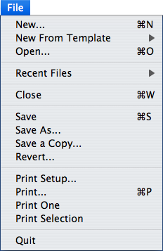 Figure 4.1: The File -menu
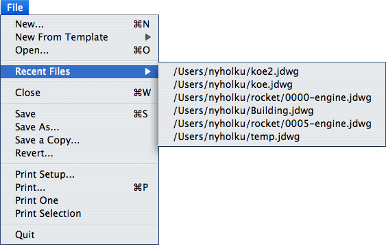 Figure 4.2: Recent Files -menu
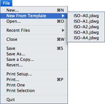 Figure 4.3: The Template -menu
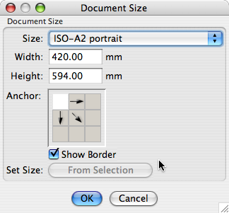 Figure 4.4: Document Size -dialog
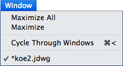 Figure 4.5: The Window -menu
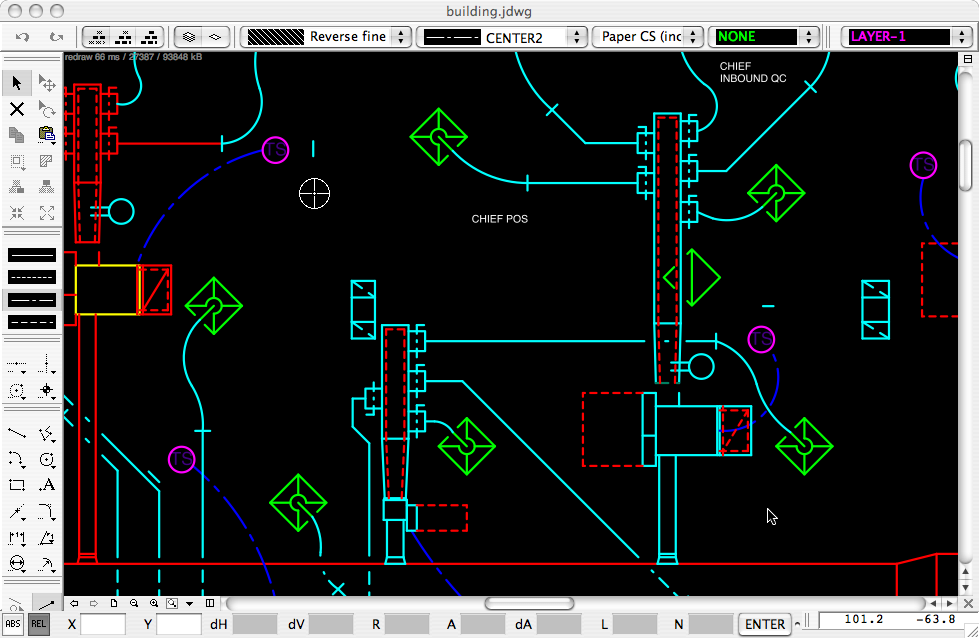 Figure 5.1: A jDraft Window
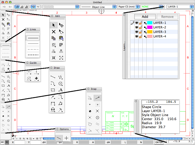 Figure 5.2: jDraft Toolbars
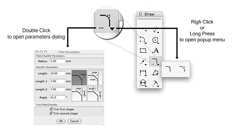 Figure 5.3: Pallets and Parameters
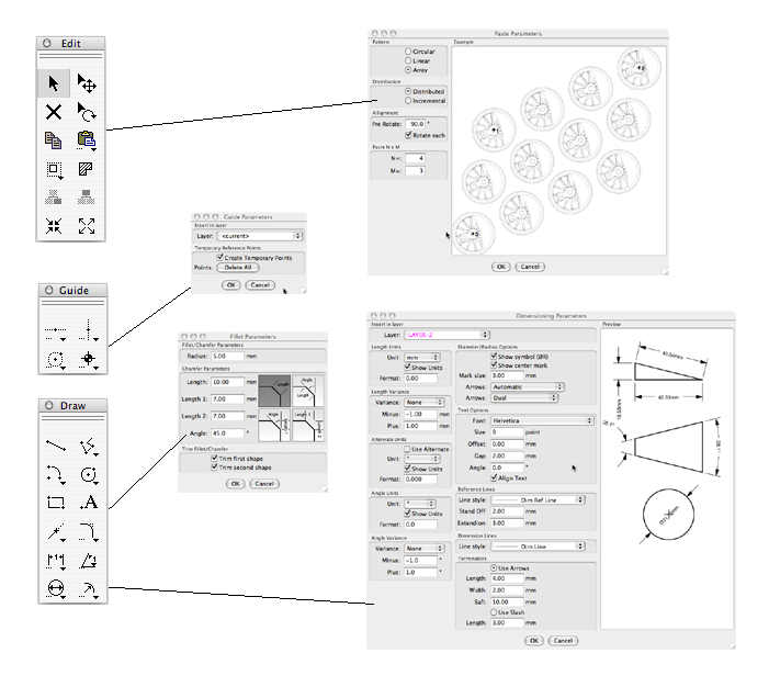 Figure 5.4: Finding the Parameters Dialogs
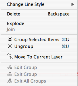 Figure 5.5: The Right Click -menu
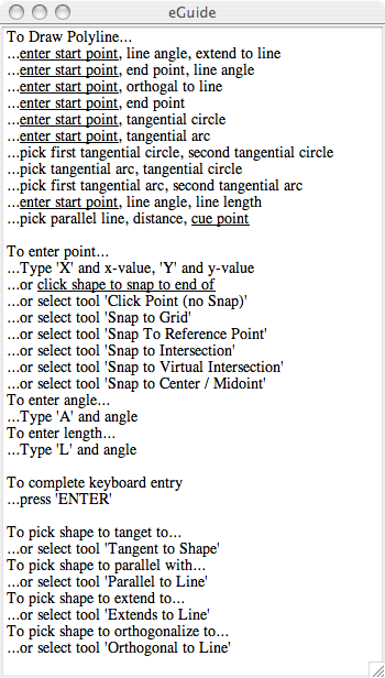 Figure 5.6: Hatching Combinations
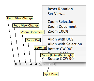 Figure 6.1: View Controls
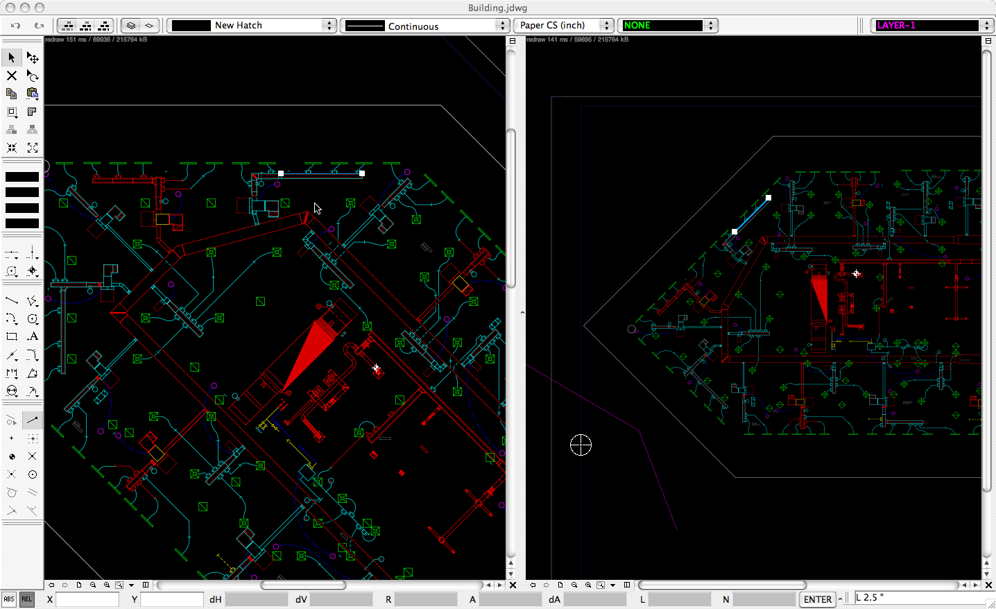 Figure 6.2: Rotated Views
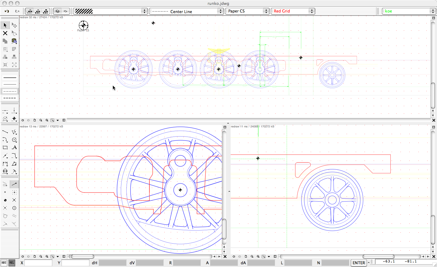 Figure 6.3: Multiple Views
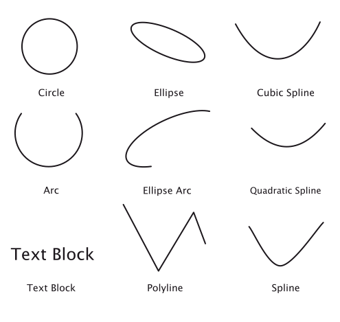 Figure 7.1: Drawing Primitives
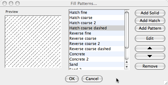 Figure 7.2: Fill Patterns -dialog
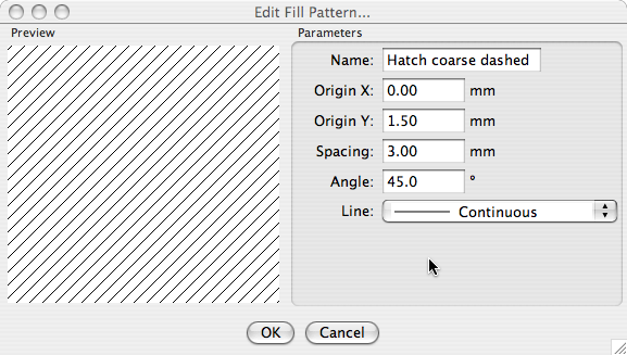 Figure 7.3: Hatch Pattern Edit -dialog
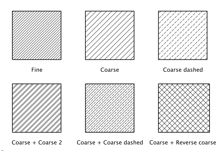 Figure 7.4: Hatching Combinations
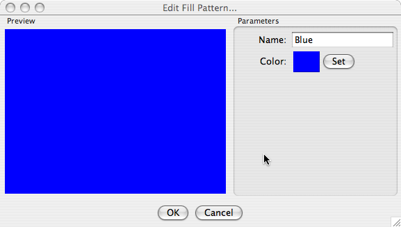 Figure 7.5: Solid Pattern Edit -dialog
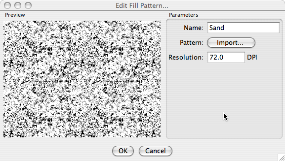 Figure 7.6: Raster Pattern Edit -dialog
 Figure 8.1: Snap -cursor
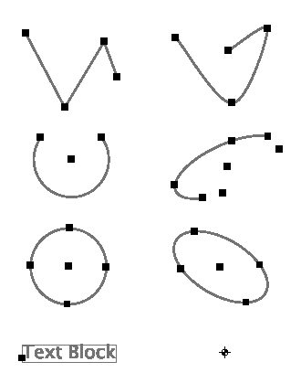 Figure 8.2: Shapes and Snap Point/Handles
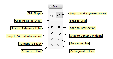 Figure 8.3: Snap Tools -toolbar
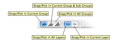 Figure 8.4: Snap Controls -toolbar
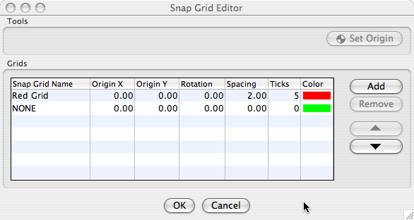 Figure 8.5: Grid Parameters -dialog
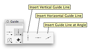 Figure 8.6: Line Guides -palette
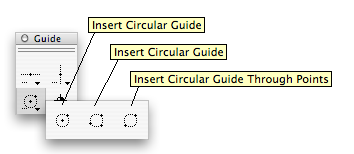 Figure 8.7: Circular Guides -palette
 Figure 8.8: Reference Point
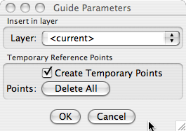 Figure 8.9: Circular Guides -palette
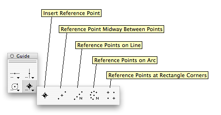 Figure 8.10: Reference Points -palette
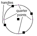 Figure 8.11: Circle Handles and Quarter Snap Points
 Figure 8.12: Coordinate System Origin -symbol
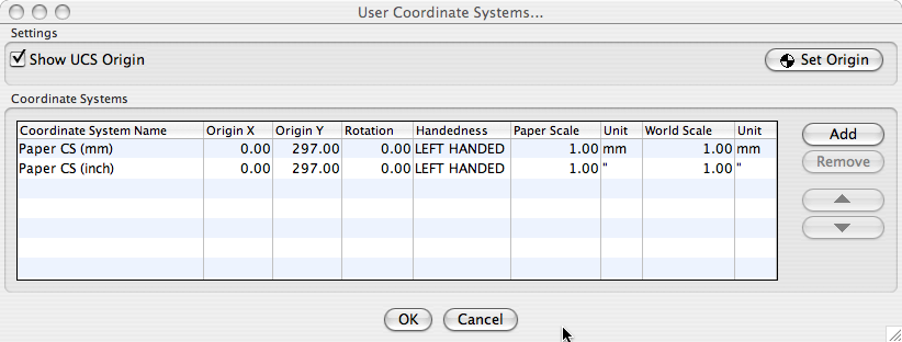 Figure 8.13: Coordinate Systems -dialog
 Figure 8.14: Last Point -symbol
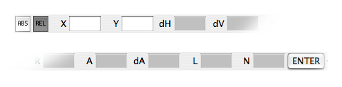 Figure 8.15: Numeric Entry -toolbar
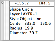 Figure 8.16: Info -toolbar
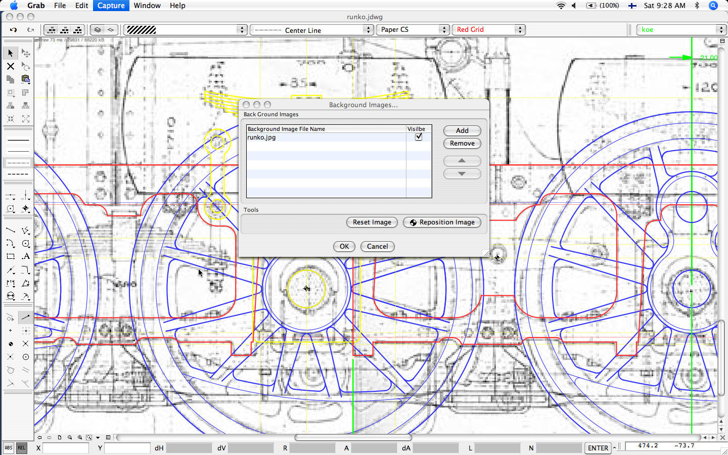 Figure 8.17: Example of Background Image Usage
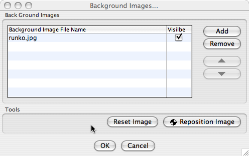 Figure 8.18: Background Images -dialog
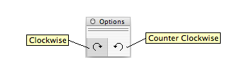 Figure 8.19: Arc Direction -options
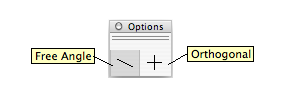 Figure 8.20: Line Constrains -options
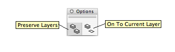 Figure 8.21: Paste Laeyr -option
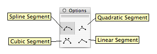 Figure 8.22: Spline Segment -option
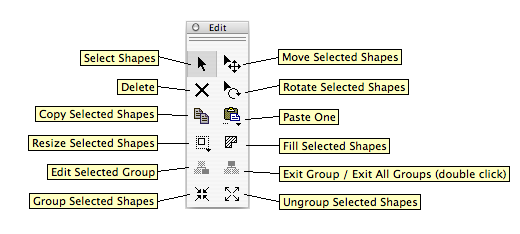 Figure 9.1: Edit Tools -toolbar
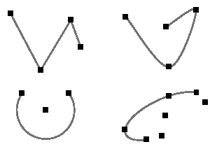 Figure 9.2: Selected Shapes with Handles Visible
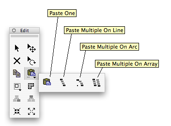 Figure 9.3: Paste -palette
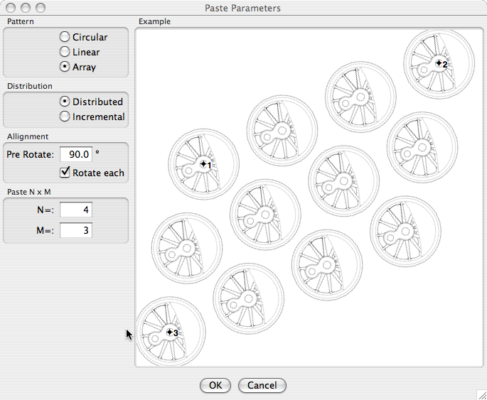 Figure 9.4: Paste Parameters -dialog
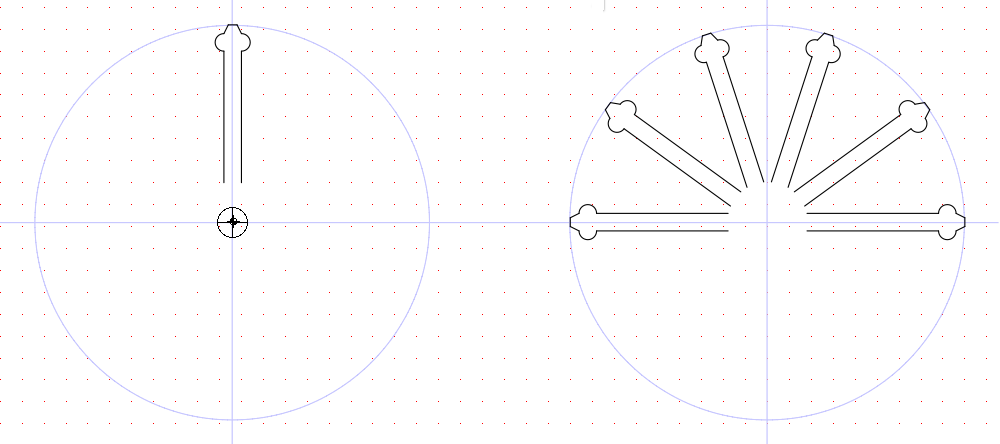 Figure 9.5: Circular Paste Example
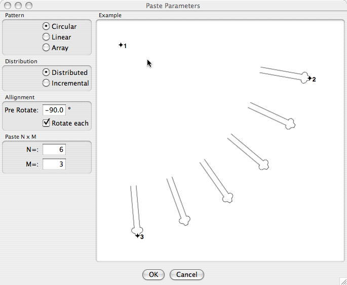 Figure 9.6: Circular Paste Parameters Example
 Figure 9.7: Numeric Entry of Angle
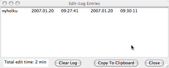 Figure 9.8: Edit Logs -dialog
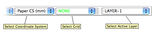 Figure 10.1: Coordinate System, Grid and Layer -controls
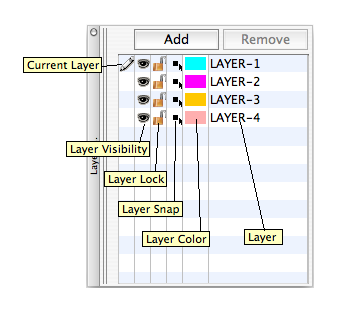 Figure 10.2: Layers -toolbar
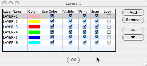 Figure 10.3: Layers -dialog
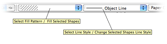 Figure 10.4: Fill and Line -controls
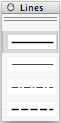 Figure 10.5: Lines -toolbar
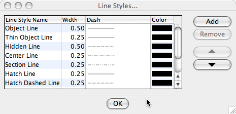 Figure 10.6: Line Styles -dialog
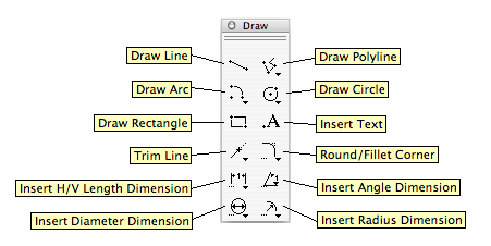 Figure 10.7: Draw -toolbar
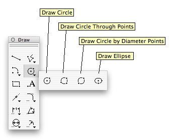 Figure 10.8: Circles -palette
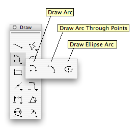 Figure 10.9: Arcs -palette
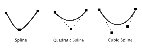 Figure 10.10: Catmull-Rom, Quadratic and Cubic Splines
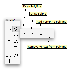 Figure 10.11: Polyline/Spline -palette
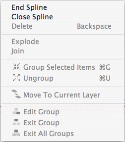 Figure 10.13: Spline Right Click -menu
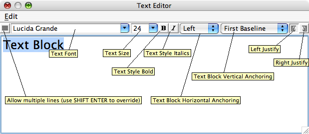 Figure 10.14: Text Editor -dialog
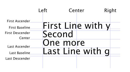 Figure 10.15: Text Block Alignment
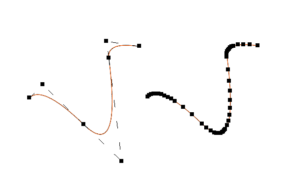 Figure 11.1: Exploding a Spline
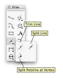 Figure 11.3: Trim and Split -palette
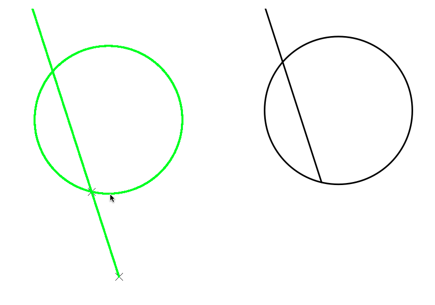 Figure 11.4: Trimming a Line
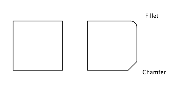 Figure 11.5: Fillets and Chamfers
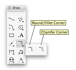 Figure 11.6: Fillet and Chamfer -palette
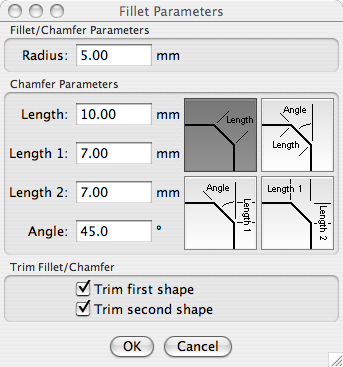 Figure 11.7: Fillet Parameters -dialog
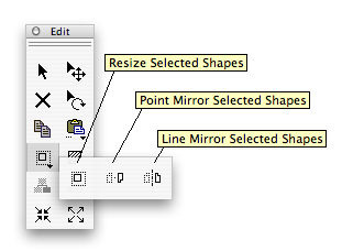 Figure 11.8: Resize / Mirror -palette
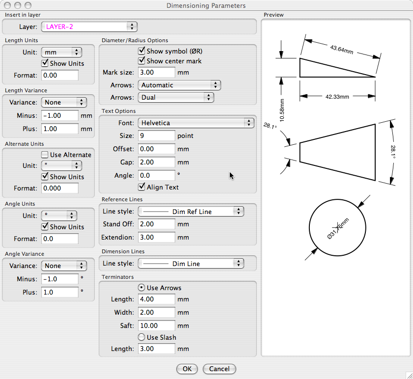 Figure 12.1: Dimensioning Parameters -dialog
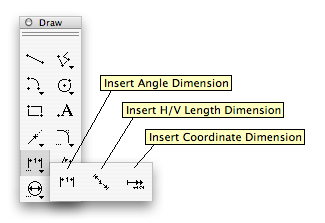 Figure 12.2: Orthogonal Dimensioning -palette
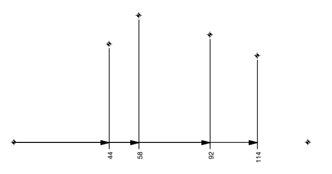 Figure 12.3: Coordinate Dimensioning Example
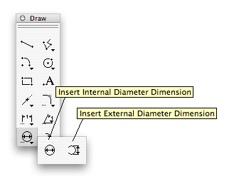 Figure 12.4: Diameter Dimensioning -palette
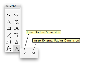 Figure 12.5: Radius Dimensioning -palette
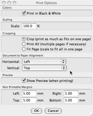 Figure 13.1: Orthogonal Dimensioning -palette
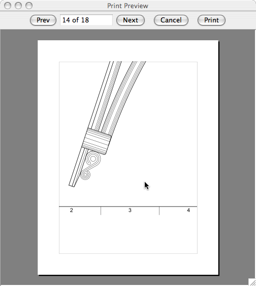 Figure 13.2: Priview -dialog
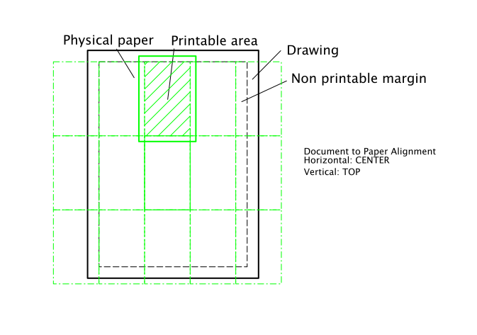 Figure 13.3: Print All On Multiple Papers
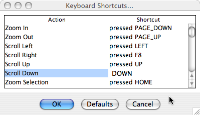 Figure 15.1: Shortcuts -dialog
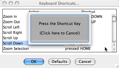 Figure 15.2: Change Shortcut -dialog