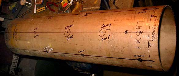
Marking out all the bushings' and domes' positions on the copper-nickel boiler tube, which is 160 mm / 6.25" o.d. and 600 mm / 23.6" long, with a 2.5 mm / 0.1" wall - strength-wise, that is equivalent to a 5 mm / 0.2" wall on a plain copper tube! This wondeful material also takes threads well, which means I can bolt the smokebox directly to the boiler tube, without a connecting ring, as is the usual practise. The front tube sheet will of course be behind the bolt holes... ;-)
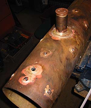
 All the bushings are turned from bronze (brass is a no-no in boiler construction!), and silver soldered in place. The steam dome is a piece of copper-nickel tubing with a bronze lid on top, and it has a reinforcement ring silver soldered at the base (I studied the Australian copper boiler code, and found many good safety suggestions there, this reinforcement among them...)
The dome tube contains baffles that will prevent water splashes from carrying over into the dry pipe, as seen on the drawing. The 3003 has a very low steam dome, and often gets wet steam, despite its superheater/dryer, so I changed the dome design for this loco - not difficult, since the 0-6-0 prototype has a very high steam dome.
I'll make a similar smokebox throttle as on the 3003, since it has functioned so well.
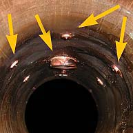
Checking that the silver solder has penetrated the joins, an unbroken ring of silver must show around every fitting on the inside of the boiler.
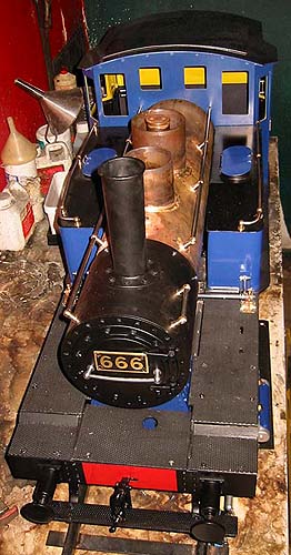
The handrails are tentatively in place. They function as control rods for the drain cocks and water pump, so I'll have to put handles on the handrails inside the cab, and levers and links on the smokebox end of the rails, which can rotate in their studs.
The steam and sand domes are only half finished, I'll have to form some brass covers for them yet... and of course there will be insulation and cladding on the boiler!
The actual functioning dome is seen inside the outer, larger one, which is just a loose wrapper for the right appearance - it's not soldered to the boiler, what looks like solder joints on both dome bases are in fact only flanges attached to the dome bases, which will later be used for attaching the domes to the boiler cladding.
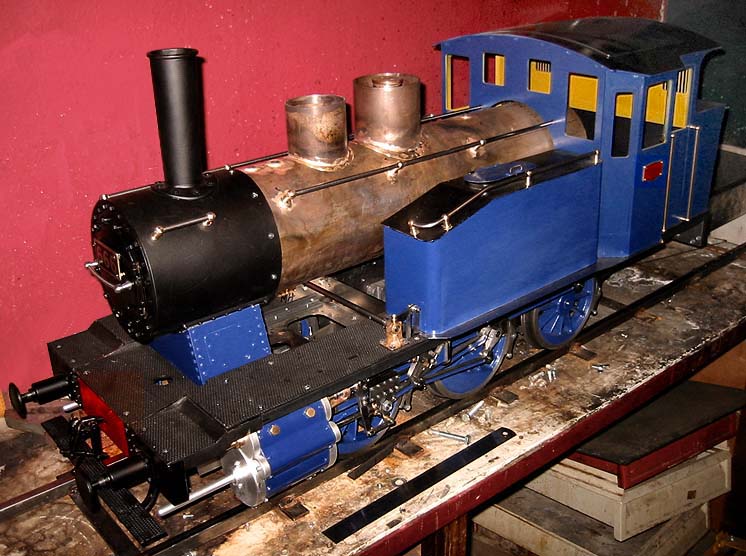 Now, this slowly starts to look like a loco! But appearances can be deceptive, there is still nothing inside the boiler, nor any valves or controls in the cab - so, until next time!