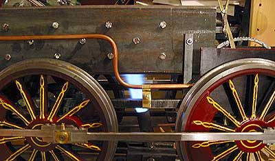
 The flash boiler I planned to use in my loco was put together already last fall (see the story lower down on this page), but not until now did I get to connect it to the loco, and try a steam-up. Not having built any proper loco-sized burners, I used a relatively large propane burner, flame diameter approx. 25mm (1"), which I attached firmly in the "split" of the workmate-type bench carrying the loco - the burner's handle extended well below the benchtop...
 The flame spread nicely into all the "flues" between the iron plates, heating an area of about 75 by 100 mm (3 x 4"). Even though I had no blower, or even the smokestack attached, the draught was adequate - in fact, the flame blew itself into the flues...
Unfortunately, the result was disappointing. I did get a few spurts of steam, just enough to run the engine a few revolutions, but nothing like continuous steaming (even with an ample amount of water in the tubes). I used a hand pump to supply water. In addition, the crosshead pump was functional and connected, but since the engine ran only a few turns at a time, that pump didn't amount to much. The "safe" water system described below wasn't necessary for the test, since I had a manometer connected to the water line and could monitor the pressure - which didn't rise much over 2 bars (30 psi) at the best of times...
The burner consumes about 400 grams (14 oz) of gas per hour. Ten minutes into the test, the iron plates glowed bright red-hot where the flame touched them, but nevertheless, during the entire half-hour test, the front part of the assembly didn't even get to boiling temperature, tested by dripping water on the iron - the "point of boiling" did not move forward during the last ten minutes, which proves that the heat input balanced the losses. Of course, the boiler was not lagged, but as discussed on one of the e-mail discussion groups I belong to, lagging has very little effect on boilers this size.
So, the heat-reserve idea obviously won't work unless you heat enough of the iron chunk directly with a flame - now, only the rear fifth of the plates were touched by the flame. Even if I'd fill the entire firebox space with burners (smaller ones, necessarily), I doubt I could get this design to work - even if I doubled the total amount of gas to 800 grams per hour. Or have you ever seen a loco with a fire below the entire boiler? ;-)
But, as I mentioned last fall, this was just an idea I wanted to try out - the cost was only $ 50 for the materials (some of it salvageable), a couple of evenings putting together the boiler, and half a day finally connecting it and setting up and making the test.
Conclusion: I decided not to experiment any more - not with flash, not with the "novel" (not so, in fact) boiler described elsewhere on these pages. That design may have other problems, so I've decided to build a very conventional boiler, with firebox, flues, steam dome - the whole kaboodle. Propane firing is still my ambition, but a boiler with firebox can be used for almost any fuel, by exchanging the burner with a grate...
Having acquired some kaolin wool, I noticed how brightly it glows when hit by a propane flame - and it's not consumed, at least in the brief test I made... Could this be a good material to make a radiating body from? An easily renewable "cage" of iron or copper wire that will hold some wool in the flame? This glowing body (placed in the position normally occupied by firebricks in a full size loco) would provide more heat into the firebox (by radiation, as opposed to convection in case of the propane flame) - I read somewhere that flues are marginal when it comes to transferring heat into the water...
Any comments? Email me at animato@sci.fi, please!
Flash boiler? 2001-09-15
 This is an idea that I've adapted and developed from an article in "Engineering in Miniature" (Aug. 2000) on how to build a flash boiler with some heat reserve in the mass of iron surrounding the tubes.
The boiler consists of 4 separate elements, each made from flattened copper tubing and two 500 mm (20") long strips of 100 mm (4") wide band iron. All elements are bolted together, and to the inner wrapper, as shown.
Water is pumped in with the crosshead pump (and perhaps also one or two axle pumps) at the bottom, and the steam escapes the elements at top. Manifoilds divide the water into the 4 elements, and combines the superheated steam to an outlet leading to the cylinders. The iron weighs 24 kilograms (50 pounds), and will thus provide an ample mass as a heat reserve. The total heating surface of, and between, the elements will be a little over 0.4 square meters (640 sq. in.) Enough? Propane firing is intended.
Since the specific heat for iron is 0.45 kJ/kg per deg. C, compared with 4.19 kJ/kg for water, the mass of iron would in fact heat up to operating temperature twice as fast as the approx. 5 liters (1.3 gal.) of water needed in a conventional boiler of this size. (Copper elements would be no better - a little heavier, but less heat capacity per kg - and I won't even calculate the cost...) Admittedly, the heat reserve, and thus steaming capacity, would be only half that of the water boiler. But I can't figure a way to get double the amount of iron into the boiler casing (nor would I be willing to lift it... ;-)
Perhaps there should be a shield (black in drawing) under the bends in the firebox end? Should I make the inner wrapper of stainless steel instead of brass - maybe that would mean less heat loss, despite the kaowool insulation? In this case, would brass be allowable - I know brass is a no-no in boilers, but here it's only the copper tubes that are pressurised, so any de-zinking or corrosion of the brass would not be a safety concern. The manifolds again are far away from the fire - is brass OK here?
Should each element be made of two U-formed tubes instead of one zigzag shaped? I'm not familiar with how water boils in a tube, nucleating, film etc. Any suggestions?
The steam pressure is regulated by the water supply only - for starting, a "priming" hand pump will be necessary. A saftey valve is installed on the water side of the elements, returning water to the tank until the pressure drops.
Flash boiler! 2001-09-27
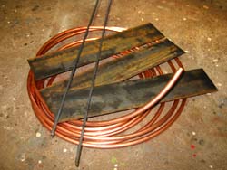 Since the cost of materials for the flash boiler described on the previous page is only around US$ 50, and the work involved is not overwhelming, I decided to try it! The picture shows what I acquired: Copper tube, dia 12 mm, 10 meters, hot rolled iron, 5 x 100 mm, 10 pieces, and 6 mm square iron rod, 12 meters.
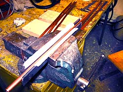 First, flattening the copper tube - this will make the heat transfer more effective than in a round tube. Since the tube (ordinary plumbing type) is annealed, it was easy to squash to the desired thickness in the bench vise - I added a couple of band iron strips to the jaws (attached with masking tape) so as not to imprint the jaw pattern on the tube...
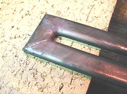 Cutting suitable lengts of flattened tube at a 45° miter enabled me to make nice, "square" bends by using the same sil-fos type solder as plumbers do...
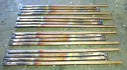 Here are the four "heat exchangers" that will be the entire pressure vessel of the boiler! Total volume of this boiler is only about 500 cc (30 cu in)! There is no risk of an explosion with a boiler of this type - if a tube or join fails, some steam will escape, but since there's only a minute volume of hot water involved, any such event won't be violent...
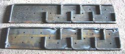 The iron plates will form a heat reserve, and by bending and tack-welding pieces of 6 x 6 mm iron to the plates, I get a zig-zag "flue" of sorts for the combustion gases. This will be much more efficient than just an empty space between the elements!
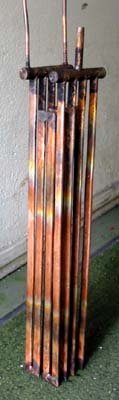
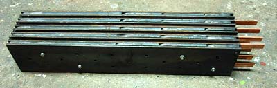 Here is the entire chunk, weighing some 30 kilograms (65 pounds), held together by just a few stainless bolts (there will be 18 of them eventually). The copper tubes projecting out of the rectangular encasement will be connected to the water supply (lower tubes) and steam outlet (upper tubes) in the loco's smokebox.
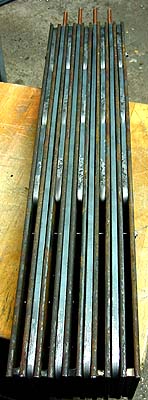
 Left image: The flue openings on the underside, to be located inside the loco's firebox, the sides of which will have thermal insulation of kaolin wool to prevent heat loss. Note that the copper tubes are totally protected from the flame by strips of 6mm iron rod. This will prevent any oxidizing and scaling of the copper. The size of the encasement is 110 x 100 x 500 mm (4.5 x 4 x 20").
Right image:
The finished tube assembly with water and steam headers & connecting tubes, directly after soldering - unpickled, dirty with oxide.
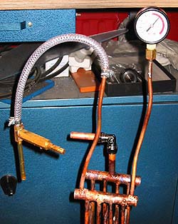 The assembly held the pressure well, after one leaky join was re-soldered. I momentarily pumped the pressure up to 16 bars (230 psi). Note the blind tube plug at the steam header during this hydro-test. The ball-valves in the little hand pump were tight enough to keep the pressure well over 10 bars for several minutes.
Safe Cold Water System for Flash Boiler 2002-01-28
This drawing is mostly self-explanatory...
The principle is simple: At the heart of the system, a small pressure reserve tank will be pumped almost full with water, the remaining air will act as a cushion, and keep the pressure almost constant, provided that the pumps supply water at approximately the same rate as is used by the boiler.
Note that the pressure in the entire system cannot rise over 10 bar (140 psi) - the safety return valve will take care of that. Even if the steam pressure for some reason (too much water forced into the flash boiler tubes) rises over 10 bar, the pressure will drop as the steam goes back into the water system and condenses.