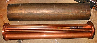
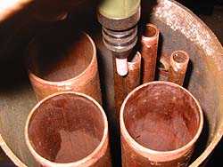
Note that there is a T-join already soldered to one of the tubes - this is the "dry pipe" that will carry steam to outlets at each end of the boiler. There will be a tube going from the T up into the steam dome.
The boiler shell has several fittings, counting from the back (below in picture) they are: backhead steam manifold, steam dome, two blind studs to attach the sand dome and the front (dummy) steam dome, and finally a water filling hole that doubles as attachment for the bell. In addition, there will be a blow-out hole in the lower back end of the boiler (not even drilled yet in this shot - its bushing will be soldered in a separate operation).
In this picture, I have fluxed all the joins, and am just about to light the propane torch... For this boiler job, I bought a Sievert nozzle a little larger than what I've been used to before - no. 2943, which burns 2 kilograms of propane per hour, generating 26.000 Watts of heat!
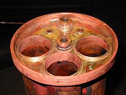
Here I have silver soldered the backhead tubeplate to the stack of tubes. Two threaded bronze connection nipples are also soldered to the plate at this time.
It is extremely important that the silver solder penetrates all the way through the joined area - here you can see the string of solder that has appeared by capillary action onto the other side. When this string is unbroken, you can be assured of a good join.
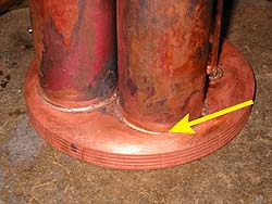
Note also that I have grooved the flange of the tubeplate; this will aid in the silver solder spreading in the large area between tubeplate and boiler shell. In addition, I filed grooves in the flange, longitudinally, so that the solder could penetrate into the grooves from outside.
How can you be sure to succeed getting the solder to penetrate with merely capillary action? The most important thing is very thorough cleaning of the parts to be joined!
In addition to "pickling" the tube plates in 10 % sulphuric acid, I used a mini-drill with a small abrasive stone running at 20,000 rpm to remove all dirt and oxide from the shell and the tubes - which were too large to pickle comfortably in their entirety... This also covered the surface with minute scratches, ensuring a flowing path for the solder even when there is a tight fit between parts.
All joins are to be fluxed immediately after cleaning, and the soldering should take place with no great delay, otherwise the flux may lose its effect.
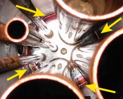
Again, the thin thread of silver (arrows) showing on the reverse side assures the join is good.
Having thus "practised" by attaching the backhead to the shell, and noted the good penetration of the solder (which, incidentally, is 40% silver, some 20% cadmium), I now feel confident that I can solder the front tubeplate both to the tubes and the shell at the same time, without the possiblility of later inspecting the joins from the inside of the boiler... (No, I don't have an endoscope... The "Rectimascop" lens I happen to own may sound like one, but alas, despite its name, it's just a widescreen anamorphic movie projector lens. And it's 4 inches in diameter... Ouch! ;-)
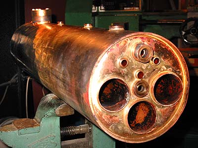
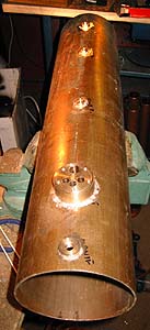
So, here is the entire soldered boiler, seen from the front. Note the large threaded bushing (12mm / 1/2" i.d.) on top front - this is the dry pipe coming into the manifold in the smokebox. The lower bushing is for feedwater - I may have feedwater heating in one of the flues, that's why I placed it here. There'll be a check valve immediately connected to the boiler at this point - do you foresee any problems with having a check inside the smokebox?
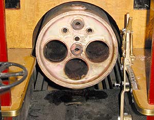
... and this is how the backhead looks at this time, inside the cab - water gauge, manometer, whistle & blower valves, and of course the propane burners are all still missing.
But, before that: HYDRO TEST! I'll have to machine some fittings to plug up all the holes, first.
We'll see if the large tubes will stand the test pressure (14 bar, 200 psi, i.e. double operating pressure) without deforming or collapsing.
Also, that will settle the debate, recently held on the groups, whether tubes of this size (39mm / 1.5" i.d.) and wall thickness (1.6mm / 0.060") will withstand that pressure, so don't miss the next thrilling episode of the 3003 story...
Close this window when you are ready...
Any information presented on this website (especially any do-it-yourself instructions) is given without any acceptance of liability for damage or injury - so, always remember: SAFETY FIRST!
The material on this page and its related pages is Copyright © 2001-2007 by J-E Nystrom. You may NOT copy, transmit and/or publish any of my images or texts in print, electronically, on your own website or in any other way. The author retains all rights to this work, with this sole exception: Storing the pages on your own computer or printing out a paper copy, for your own, strictly personal use is allowed.
You may, however, freely link to the "Building Live Steam Locomotives" page at: http://www.saunalahti.fi/animato/steam, or to my Animation Home Page at: http://www.saunalahti.fi/animato. You should NOT link directly to THIS page, since it's address may change in the future. Also, you may not put any of these pages or pictures into "frames" on your own website.
Thank you.