
First, I decided to use a superheater after all - the original 3003 had none, but neither was it propane fired... ;-)
So, three U-formed 1/4" copper tubes sil-fos soldered to the 12 mm steampipe did the trick - not very beautiful, but...
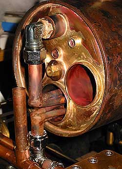
... they form a flexible joint between the throttle valve and the T-pipe leading to the steam chests. I have used ordinary water pipe compression fittings, time will tell if they're durable in this environment!
Above is a sketch of the throttle I've used. The throttle bar, which is attached to the bullet plug of stainless steel, goes all the way through the dry steam pipe to the backhead end of the boiler. The PTFE valve seat ensures a steam tight valve, when closed.
I have also attached the boiler to the frame, with flexible joints, allowing it to expand freely when heated.
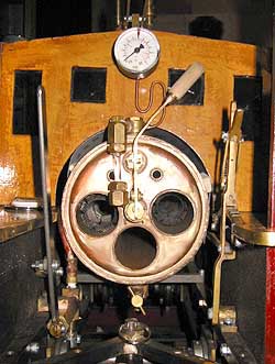
This is the boiler backhead. As you can see from this shot of the inside of the cab, I've opted for simple solutions wherever possible:
- manometer from a commercial compressed air regulator
- simple water gauge (diagonal background, and blow valve still missing)
- throttle lever with wooden handle, spring loaded to shut off steam if not held open
- blow-out cock on bottom of boiler
- hand pump on left side (handle is temporary)
- circular bubble level on left side bench - this will help judging water level in boiler
- reverser (and cylinder drain lever hidden behind it) on right
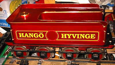
I also painted and lettered the tender, and put a lid on, so that I could show some visible progress at the Porvoo Steam Festival, where the 3003 was on display, unfinished, for the second year.
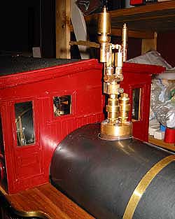
For that same reason, I installed a temporary boiler cladding, painted in what I've determined to be the right color for "Russia Iron" - a greyish, metallic, dark blue-green hue, a rather un-saturated color. This is very different from the bright blue cladding seen on some American 4-4-0 boilers, but should be truer to prototype. A few brass bands improved the appearance enormously...
The necessary fittings are now on on the steam dome - 2 steam whistles and the prescribed two safety valves (described on a previous page). In order to avoid condensation in the whistle stems, I made an unorthodox whistle valve: on the side of the whistles! The top of the steam tube is T-shaped, and two spring-loaded valves are screwed into the top. The valves have an opening on the side, going to a very short whistle stem. This will make the whistles sound immediately when operated, and not bubble and hiss a while at first...
During the past weeks, I have tested several configurations of pokers and burners - a few days ago I finally hit upon a functioning design. Having quickly put together a new poker, somewhat different from the earlier experiments, I stuck it into the lowest of the 3 flues...
Still some fiddling to do - with full pressure, the flame tended to burn more strongly in one end of the poker, but on 1 bar (14 psi) of gas pressure, I got it to burn passably even... I thought, darn, why not leave it there for a while and see what happens!
Lo and behold, this one single experimental poker, on half power, got the safety blowing (at 6.5 bar, 90 psi) in about 15 minutes! I don't think I'll have any problems keeping up the steam with THREE pokers on full power...
So, I have now tested both whistles (ouch, my poor ears!), and run the engine on STEAM (but only on the bench, so far). I got a very nice steam plume from the stack, since the exhaust steam pipe goes almost to the top of the stack, so as NOT to generate a draft in the flues - the venturis in the burners take care of that, with extra draft there is a risk of blowing out the fire! I also noticed that the engine runs much smoother on steam than on air - thanks to the expansion of the steam, obviously.
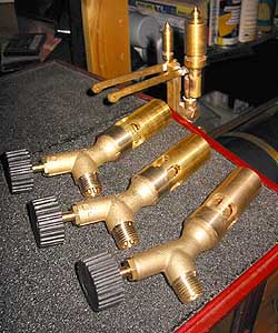
Today, I fabricated the three final propane burners for the pokers, having conducted enough experiments to determine the propane orifice (0.4 mm), the air intakes (6 slots ea. 7 x 14 mm), and venturi size (8 mm).
The regulating valves are cannibalized from inexpensive propane blowlamps (a complete lamp is only $ 17), and modified to fit the loco, but the lamp burners were discarded (flame too small), and my own design substituted.
Next step: making three proper pokers and installing them permanently in the loco. I hope to be able to run on steam within a week...
So, my esteamed friends - 'til next update!
Close this window when you are ready...
Any information presented on this website (especially any do-it-yourself instructions) is given without any acceptance of liability for damage or injury - so, always remember: SAFETY FIRST!
The material on this page and its related pages is Copyright © 2001-2007 by J-E Nystrom. You may NOT copy, transmit and/or publish any of my images or texts in print, electronically, on your own website or in any other way. The author retains all rights to this work, with this sole exception: Storing the pages on your own computer or printing out a paper copy, for your own, strictly personal use is allowed.
You may, however, freely link to the "Building Live Steam Locomotives" page at: http://www.saunalahti.fi/animato/steam, or to my Animation Home Page at: http://www.saunalahti.fi/animato. You should NOT link directly to THIS page, since it's address may change in the future. Also, you may not put any of these pages or pictures into "frames" on your own website.
Thank you.