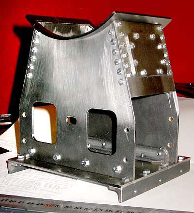
The saddle consists of just a few pieces of laser-cut plates, assembled with angle irons and M4 bolts where these won't show, and with smaller bolts on the visible surfaces. These are closer to scale size, but are still a bit too big, admittedly. But hunting for scale-sized bolts is both time-consuming and expensive, so this will have to do - the main thing is that the loco looks "real" from some 5 ft. away...
(Hey! I could always make my own, scale size fasteners! But then, the loco wouldn't probably be finished until 2008 or so... ;-)
Note how I have beveled the edges of the plates to 45° (angle grinder work), so there are no out-of scale plate edges showing on the visible part of the saddle. The saddle's semi-circular "collar" is still loose, but will be attached and adorned with bolts, too, eventually...

The smokebox tube is a piece of the same copper-nickel tubing as the boiler (yet to be built), but I split it along its length and silver brazed in an extension piece so that the boiler tube will slide into the smokebox, and the cladding will come to the same outer diameter, just as in the prototype.
I haven't yet attached the horn blocks (seen inside the frame, loosely hanging on the axle boxes) - I'll wait until I have the coupling rods done, in order to get the positioning as precise as possible, to avoid any risk of binding.
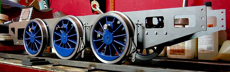
The frame was easily to assemble, thanks to the pre-cut parts. Note the heavy bolts in the rear - these will take the force from the coupler pulling the whole train of cars and passengers. All the heavy bolts will be hidden behind wheels, cylinders and other accessories - in addition to being painted black just as the frame. This is my excuse for going "over scale" with most of the fasteners.
I have tentatively attached a couple of brake hangers and shoes - the hanger's top pivot will be much sturdier than this eventually! The brake shoes are spring loaded (a coil spring is hidden in a milled recess in the lower half of the shoe), so they won't "flop over" and drag against the wheels when the brakes are off.
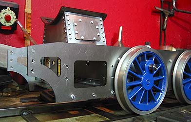
There's plenty of room inside the saddle for steam and exhaust couplings from the cylinders. I will also build a mechanical lubricator, and a good place to put it might be inside the saddle - filling would be through the removable lid on the saddle side.
Enough "website designing" for now - gotta go and drill a few more holes still today!