Created 23.5.2003
 SC1 - a Shareware Controller
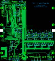
This an introduction to the SC-1, a multipurpose dual personality
shareware microcontroller board. This is not a DYI electronics project
page or build instructions for anything. The main purpose of this page
is to introduce anyone interested to the SC-1 board and provide
inspiration and pointers to related stuff plus background information
and motivation for the design choises that I've made and which anybody
who wants to use this board needs to consider.
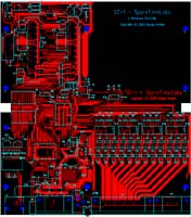
The design, schematics and PCB layot along with some
documention is available here for the interested. I have some board
available at production cost. This is by no means any business, all
information on this site is provided purely in the spirit of sharing
what I've done, an the limited supply of boards that I have is made
available only in the same spirit.
The schematics and
PCB layout were created by me and you should remember that I have no
formal qualifications for the job, so
if you embark on utilizing, in anyway, any part of this design, you are
totally on your own. Absolutely no guarantees, except that I can vouche
for having tried to provide true story here. Having said that, I must
say that I'm reasonably satisfied myself with the overall board design,
schematics and PCB layout.I think it might be used as basis for e.g. a
university level embedded system project.
As the schematics and layout are available , you can and
should use your own judgement to
see if they are worth anything to you. This is definatelly not a
project for beginners and newcomers.
The style of writing in this page is aimed to experienced hobbyist,
pros and experts should look elsewhere and not spoil their day with
this kind elementary stuff ;-)
Note that to utilize this board potentially quite a lot of
software is required; this page mainly deals with the hardware aspects
of SC-1. Maybe some day I will write about the software and maybe even
make some software available. At very least I try to provide enough
information to bring the tools and board alive with GNU tools. Someday.
I touch a lot of subjects here ranging from DC-servo motors to
IrDA communication and quadrature sensors. While briefly introducing
the concepts this page does not try to provide tutorial on those, for
all of these subjects there is a lot of good, even excellent tutorials
on the web. Not to mention that I'm no authority on any of these, just
standing on the shoulders of giants and paroting stuff.... ;-)
Get the Documentation
These links will open in a new window.
Schematics
as a PDF-file
PCB layout as a PDF-file
I/O-Cross Reference by MCU pin
Connector Cross Reference by con/pin
Bill of Materials
Shopping List
Power Budget
Links to Datasheets and Stuff
How this Board Came to Being
Every now and then, say more than twice each year, I get this idea that
I could hook up a couple of parts, an MPU, some I/O to do something
interesting. Lately I've not managed to do much in that line, maily of
course because of lack of spare time;-), but also, because
I do not fancy wiring complex circuits. Wired (at least if wired by me)
circuits take a lot of effort to complete, are unreliable and difficult
to trouble shoot. And if, against all
odds, one manages to come up with something that would be worth
reproducing, they are not reproducible.
Of course there are a lot of microcontroller boards around, so
who needs one more? I had a look around, but did not like any that I
found. Some were too
pricy, some did not have the features I wanted. Besides, designing is
half the fun the other part being construction. Anyway, sane or not, I
deciced that I would have a go at designing a kind of hobby board with
some interesting I/O and manufacture some PCBs. The result was SC-1 and
this page.
Dual Personality?
Besides being a Swiss Army Knife style all round hobby board this board
is also to function as the heart of my four axis CNC milling machine
project and some of the I/O has been designed for that purpose in mind.
My philosophy was to make it a good CNC controller first and a nice
hobby board second. But actually the design came up quite nicely
balanced so that the dual goals did not intefare too much. I least I
think so.
System Block Diagram
Below is a block diagram of the board. Most of the blocks are optional,
the idea is that the board is
configured with jumpers but of course you can configure it by
installing only the necessary parts, depending on your application.
![]() The board naturally centers around
the micro controller unit (MCU), which is basically the only
non-optional part of the board. In addition to the MCU, which contains
both FLASH ROM and RAM, there is room for external RAM and ROM, and
some potentially interesting I/O, including both voltage and current
mode analog inputs and outputs, digital I/O, relay/solenoid drivers for
outputs, HALL/opto fork compatible inputs, twelve half bridges for
motor control applications, IrDA compatible infrared communication and
Ethernet! There are on board regulators and a switch mode (step down)
converter, just in case. And if you still think you need more I/O there
is a connector for LCD character displa, hex keyboard and SPI interface
connector for expansion purposes. Plus a RS232 compatible serial port
for hooking up a PC in case you need to do some software development
;-)
The board naturally centers around
the micro controller unit (MCU), which is basically the only
non-optional part of the board. In addition to the MCU, which contains
both FLASH ROM and RAM, there is room for external RAM and ROM, and
some potentially interesting I/O, including both voltage and current
mode analog inputs and outputs, digital I/O, relay/solenoid drivers for
outputs, HALL/opto fork compatible inputs, twelve half bridges for
motor control applications, IrDA compatible infrared communication and
Ethernet! There are on board regulators and a switch mode (step down)
converter, just in case. And if you still think you need more I/O there
is a connector for LCD character displa, hex keyboard and SPI interface
connector for expansion purposes. Plus a RS232 compatible serial port
for hooking up a PC in case you need to do some software development
;-)
What could be done with the board
Given the I/O briefly listed above, what could one do with it? Here are
some of the applications I had
in mind. Naturally some of these are mutually exclusive so before
getting too exited you need to check out the schematics and datasheets
plus board layout to see if it realy is possible.
Robotics with RC-Servos
You can control up to eight RC (Radio Control) servos. These are simple
(to use) devices, they just need 6 volt in (the 5 volt available from
the board should be ok) and a pulse whose width determines the
position. There are eight PWM (pulse width modulation) outputs on
connector J8. There are lot of good tutorial on RC servos on the net so
I won't go into details here.
Motors, motors, motors
There is a dozen half bridges that can sink and source up to XXX amps.
These are connected to PWM outputs of the MCU and offer a lot of
interesting options. At one extreme you could control the speed of up
to twelve permanent magnet DC motors and on the other extremen you
could drive three 2-phase bipolar stepper motors. Or four 3-phase
bipolar stepper motors, or two 5-phase! Mount an Agilent HEDS
quadrature pulse encoder to the saft of a DC motor, hook it to the MCU
quadrature inputs and create a closed loop servo motor (or two) for
that high speed X/Y table you are planning. Or control (open loop) the
speed and direction of six DC motors, make a Lunar roamer.
Back to the 70's
Use the two AD converters to digitize your music, write a piece a FFT
(Fast Fourier Transform) spectrum analyzer software and use the sixteen
hi current drivers to blink 55W / 24 V car halogens 'nsync to your
favourite disco beat. Actually the board layut probably cannot handle
that much current but you can always supplement it with extra wiring.
MP3 player
How does a web based MP3 player sound to you? Probably awfull because
the on board DA converters are only 8-bit ones, but you could wire some
neat DA converters from Analog Devices to the SPI connector and make
your own MP3 player. Or, do you too hate those speaker cords that crawl
all over your flat? Connect the DA output to an amplifier and hook the
Ethernet controller to WLAN (you do have WLAN, don't you?) and presto,
wireless speakers! Darn it, forgot the batteries, you still need the
power from somewhere. There is always a catch somewhere!
Remote control your remote control
Well, not quite but, use the IR transmitter to talk to your VCR (Video
Casetter Recorder) remote control receiver and program it via internet
using an embedded web server running on the board. No longer do you
need to remember to program it to record that 70's show before you
catch the bus, you can do it all from the office at company time!
Remote control that old amp you built
I have this amplifier that I built long time ago. It uses a Motorola
TC5500, if I recollect correctly (IIRC) pre-amp which has voltage
controlled inputs for volume, bass, treble and balance. This board
could be used to receive signals from a standard TV/radio set IR remote
controller and control this amplifier. And the stepper motor driving
capabilety could be turned into a CD jukebox system. Only that the
simplest way to create a jukebox is to turn your PC into one, just MP3
all your CDs and store 'em a 40 Gig hard disk. Nothing to it. Sigh!
GSM Micromouse
Use the IrDA connection to connect to your mobile phone and give your
micro mouse robot a global communication channel and cheat your way
through the maze. Under Class B Division rules this is allowed, if you
do not harm the local space time continuum.
a Weather Station
Turn the board into a weather station by hooking up some sensors to the
SPI bus. With a LCD display and hex keyboard you can then read and
record the weather from the convenience of your lazy chair. Or make it
to a web server and check the weather back home, no matter where you
are. And while you are at it, why not add a photo diode to one of the
inputs, put it next to your house kW-meter that has the blinking LED
indicator (at least mine has) and monitor the power consumption of your
heating system.
Digitals scope or data logger
The next time you debug your lates circuit why not first make a digital
lloscope from this board, would it not be nice to be able program you
scope to catch just that ever so rare glitch that only happens under
this or that condition? Actually, this maybe already a past dream as
there are ridiculously cheap gadgets
(aka oscilloscopes) that plug directly to USB connector. But
a datalogger for the next launch of your high power rocketry project?
That too maybe a bit of the mark as there are very nice
PIC based loggers that hook between your keyboard and the PC
so that you get the data directly to Excel. But still Daddy, I want to
do this all by MYSELF...Or monitor your camping propane container
turned to gas turbine!
The above are just some of the possibilites that I had in mind
when designing this board. All you need is some imagination and of
course it helps if your know your digital circuits and can do a litle
programming. Software is actually what this board is all about.
Walk Through the Design
The Power Supply
Strictly speaking there is no power supply on board but there are
voltage regulators, rectified power needs to be supplied to the board
through J20. The DC input is protected by against wrong polarity by D6
which has a current rating of 1 Amp. If you need more current and you
can of course change the type or replace it with wire althogether. (For
example MBRS340TR has a rating of 3 Amp at 40 V, it comes in a SMC
package instead of SMB but you should be able to solder it in.)
The board is designed to be powered from 9 - 36 V DC supply.
The higher the voltage the more losses you will have on the linear
regulators and thus more heat. As there are no heat sinks this puts a
limit on either current consumption or supply voltage. Maximum input
voltage of 36 V DC allows the use of simple rectified 24 V AC with
sufficient filter capacitors (mind you if the line voltage is 10% above
nominal you may be stretching your luck as some components might be
over max spec). The minimum operating voltage of 9 V DC allows the
board to be run from single 9 V block or 12 V car battery.
A word about the linear regulators. I chose to have them all
of type LM317 which is adjustable, so that I need not to purchase three
varieties. More components (two resistors) but they also have the nice
feature that they can be used up 40 V input voltages, more than most
fixed voltage regulators. In theory they can put out .5 Amps but the
chosen D-pack (TO-252)package (without heat sink) limits the max power
dissipation to about W at room temperature. So with 34 V input voltage
you can only draw about 30 mAmps from the 5V line, hardly enough to
power the MCU.
5 Volt regulators
The 5 V regulator feeds the MCU, external RAM/ROM, (off board) LCD
display, Octal drivers, RS232 port and IRDA tranceiver + the
encoder/decoder, so it is pretty vital piece. Depending on the current
consumption you can get away with a linear regulator (IC17,R53,R72,C15)
or if need more current, say you want to drive RC-servos with the board
and solder on all the possible bells and whistles, then you need the on
board switch mode regulator (IC19,C21,D3,R74,C19,C20,C14,C13,C16,L1).
You need to decide and install only the approriate components. See
power budget below for details on estimated power consumption of
different parts on the board.
3.3 Volt regulator
The 3.3 V is only needed by the Ethernet controller and associated
parts, so if you do install them you can leave the 3.3 reg out
(IC20,R79,R80,C17). Actually, the 3.3V regulator together with the 100
mA drawn by the Ethernet chip limits the maximum allowable DC input
voltage to the board to about 14 Volts, otherwise it may run too hot.
If you need higher input voltages and install the switcher for the 5
Volt, then you can/should wire (sorry about that) the 3.3 V regulator
input to use the 5 V instead of the board input voltage (V_DC).
12 Volt regulator
The 12 V regulator supplies the half bridge drivers
(IC12,IC13,IC14,IC15), the (off board) position reference sensors for
motors and the opamp (operation amplifier) that is used to buffer the
DA outputs.
All the voltages (except 3.3V) are available (via jumper configuration)
at the I/O connectors (J8,J10) for use as supplies to the off board
devices (relays, solenoids etc). At below 14 V input voltages (to the
board) this regulator is not able to regulate anything, so you might
just replace it with a piece of wire. The bridge driver work down to 7
Volts and most opamps too, so operation down to 9 volt in to the board
even with the 12V regulator installed should work ok.
There is no particular reason for the 12V to be 12V, you can change it
from by changing the voltage dividers (R15,R13), just check that all
components fed by the 12V line will remain within spec. You migh, for
example, want to raise the voltage to 15V if you need higher output
from the opamp and use one with whose output high does not reach the
rail voltage.
MCU
MCU stands for Micro Controller Unit as opposed to CPU or Central
Prosessing Unit, implying that it is in fact a system-on-chip (in case
you have missed this piece of semantic pedantry ;-). The chosen MCU
(IC10), Hitachi H8S 2398, is pretty much a system-on-chip, depending on
which kind of system you want. In addition to the powerfull CPU it has
got 256 kB Flash ROM, 8 kB RAM, three serial ports, versatile timers,
lots of I/O etc, etc. For a minimal system you do not need much more
than the MCU and the clock (X1,C28,R93) plus reset circuits
(IC16,C11,R52,R39) plus the serial port (to be able to download some
software. Actually, I plan to built my CNC (Computerised Numerically
Controlled) milling machine using just the MCU, the serial port and the
half-bridge drivers.
Internal Flash
According to the MCU datasheet the internal Flash can only be rewriten
about 100 times, which is plenty if you just need to download the
software once but seems way too low number if need to do some software
development. However a knowledgable friend said that what the spec
actually means is that the manufacturer guarantees that after 100 write
cycles the data will be retained for 10 years, if you perform more
write the data retention will gradually get shorter, he estimated that
after a 1000 writes it might be down to year or so. I have high
confidence on this friend and I'm going to try my luck, but if you feel
differently you need to solder in the external Flash and do your
software development there.
MCU operatin modes
The MCU can operate in various modes. You can run it in single chip
mode in which you have more I/O pins available, or in external bus mode
in which you can have external RAM/ROM (in external bus mode you can
use either 8 or 16 bit bus width) and you can boot it up in a special
bootstrap mode in which software can be downloaded using the serial
port (J22). The operating mode can be configure with jumpers
(J115,J16,J24). Without any jumpers installed the mode will be XXCHECK.
The viable modes in which the board is designed to be run in are either
single chip or 8 bit external bus mode. And of course the boot
variaties of these to download at least the initial software. The 8 bit
external bus mode is mainly aimed for the Ethernet controller.
External Memory
External here means to external to the MCU chip. There is room on the
board for two 512 kB JEDEC standard chips (sorry no sockets, either you
solder them on or not). You can thus have MB of RAM or (Flash) ROM or
512 kB of each. This should be plenty, actually I think I will never
need them, but there they are, just in case like Pope's...
Solenoid Drivers
To drive (relatively) high current and inductive loads, such as relays,
solenoids and magnetic valves, I incorporated two Motorola MC33298
chips (IC2,IC3) to the design. Intenally (on the board) they are
connected to the SPI bus, which makes sence both in PCB real estate
sence and in that there can be no need to switch these types of loads
at high frequency, so SPI is fast enough. These chips have so called
lo-side drive transistor ie the load is connected between a supply
voltage and the output, which the driver then pulls down.
The outputs are protected against inductive spikes and short
circuit (the chip was origanlly designed for automotive applications
where ruggedness is vital). The short circuits protection turns of an
individual output in case of a short. However, it is possible to
destroy these chips with thermal overloading if you keep turning on the
shorted output. Even though it turns off automatically it may
eventually generate enough heat to destroy the chip. Keep this in mind
when developing the software.
The chip has some built in diagnostic capacity in that if an
output is in the off state you can check weather a load is present or
not. And if an output is in on state you can check if it is shorted or
not.
Despite of the immediate and fast over current protection it
is possible to drive also loads with high initial (inrush) current,
such as incandescant lamps. For this purpose you need to install the
jumpers (J12,J13) to place the drivers in linear current limit mode.
In theory these drivers can drive 3 amp from each output pin.
The Rds_on is 0.45 Ohms per output so the power dissipation is 4 W at
max current which is quite a lot of heat, but you can parallel the
outputs at will, so you can get this down to 0.5 W. With a maximum
usable supply voltage of 50 Volts this gives 150 W of controllable
power. With two chips that is 300 Watts, not much for disco but
probably enough to discofy your T-bird not to mention controlling a
dozen or so magnetic valves for automatic watering of flowers or a
drink dispencer! Actually the board layout does not support this much
current but you can augment the board with external wiring. Check the
layout before attempting high currents.
Analog Inputs
There are four plain analog inputs (J8-39,J8-37,J8-35,J8-33) that are
directly connected to the AD (Analog to Digital) converter inputs pins
on the MCU. The converter on the H8S is a 10-bit one, so it is very
nice, but the board layout and your wiring probably wont't allow this
level of precision not to mention the noice. These inputs are protected
by the TCF6000 (IC4) diode network that clamps the signals to +5V and
ground. To use these inputs you connect your signal source (a voltage
source) between the input and ground.
These signals can also be used as general purpose digital I/O
pins.
Inputs with 4-20 mA Loop Cmpatibility
Two more analog inputs are provided (J10-37, J10-33). These inputs are
provided with shut resitors to ground the idea being to use them as
industry-semi-standard 4-20 mA loop inputs.
The 4-20mA loop, for the uninitiated, is a simple two wire
scheme which provides power to a sensor and the signal from the sensor
over just two wires. The scheme is that an unregulated voltage is alway
provided between the two wires and the sensors can use this voltage to
power its internal electronics or any local circuits it needs. The
signal is transmitted by modulating the sensors current consumption
proportionally. The great advantage of using current as the signal
carrier is that it is immune to electrical (capacitive or inductive
overhearing) interference, because the current modulator at the sensor
side will compensate for any noise. As (almost) any sensor is bound to
use atleast some current, 4 mA has been defined as the zero reference
and 20mA as the max scale for the current loop interface.
To use these inputs the sensor (or whatever) is connected
between the input and a supply voltage. Any current consumed by the
sensor is visible as voltage loss over the shunt resistor (R90,R91) and
can be digitized with the MCU analog inputs. This simplistic
implementation (on this board) sacrificies 20% of the AD converter
range because the zero point (4 mA) is not compensated for in anyway.
But the simplicity is worth that I thought. And if you do not mount the
shunt resistors you can use these in the same manner as the other
analog inputs (and also as digital I/O). Also these inputs are
protected by a diode network (IC24).
Analog Outputs
Two analog outputs are provided (J10-39,J10-37), which are connected to
the DA (Digital Analog) outputs of the MCU. The DA converters are only
8-bit ones, but that is enough for most applications.
Either buffered voltage mode or 4-20 mA current mode is
available, configurable with jumpers (J4,J5).
In the voltage mode (jumper between pins & 2) the
output voltage depends on the voltage divider (R86/R89 and R88/R87) and
is of course limited by the installed opamp (IC21) output capacities
and the 12 Volt opamp supply. To use this mode the load must be
connected between ground and the output.
In the current mode (jumper between pins 2&3) a
transistor (Q1,Q2) functions as an open collector controlled-current
sink. The current is controllable between 0-20 mAmps making it
compatible with the 4-20 mA loop spec (if there is one, it is such an
ancient thing). To use this output mode the load needs to be connected
between a supply voltage and the output.
RS232C Port
A RS232C compatible serial port is available (J22) for connection to a
PC (Personal Computer) with a stanrad 9 pin cable. The board is wired
as DTE (Data Terminal Equipment)with a male connector, same as a PC, so
a cross cable with female connectors is needed. This port and cable
could also be used to hook two boards together. CTS (Clear To Send) and
RTS (Request To Send) handshake lines are provided. The serial port is
wired, via RS232C transceiver (IC25) to the MCU serial port , which
makes it possible to use it for bootstrap loading also.
IrDA Port
The MCU serial port 0 is connected to an Agilent IrDA encoder/decorder
(IC22) which inturn can be configure with jumper(J3, between
2&3) to drive an Agilent IrDA transceiver (IC1). This should
enable you to use your GSM cellular phone as a wireless modem with the
board (no strings attached, pun atempted) or talk to your laptop PC to
exchange files, for example. If you don't want the IrDA you can leave
out the encoder/decoder.
IR-remote control
The above mentioned IrDA transceiver, which is litle more than a high
curren IR LED and an IR-photo transistor in the same package, can also
be connected via jumpers to the MCU I/O port.
My bright idea was that to be able to send IR remote control
commands to your VCR or TV would open up interesting possibilites. And
to be able to receive command from standard remote conrols would make
it possible to command the board with an off-the-selv remote controller
(like the one that was left over from that TV set that was dropped out
of the window when the license inspector knocked on you doormitory
door).
You have the choise of two outputs and two inputs to
drive/read the transceiver. The reason is that to drive the transmitter
IR-LED you probably would like to use one of the TPU (Timer Pulse Unit)
outputs in the MCU, which means the pin in question cannot be used for
anything else. So you need to sacrify something, basically either one
of the half-bridge drives or one of the (possible) RC-servo outputs. I
couldn't decive which, so I put in a jumper header (J6). Now you can
choose.
The same reasoning applies to reading in the IR-opto
transistor, you would probably want to use the pulse counting facilites
of the TPU to receive the data but do you want to sacrifice one of the
quadrature inputs or one of the half bridges. As answer dependce on
what you want to do I put in another jumper header (J1).
I have to confess, I'm a bit out on a limb here as I haven't
got any experience with either IrDA or remote control IR application in
general. Just thought that might interesting to experiment with those
too.
Dozen or so Half Bridge Drivers
There are twelve of these to be exact. Why twelve? That is because I
want to drive both three and two phase stepper motors with this board
and to drive a bipolar (is there any other kind) 3-phase motor you need
three half bridges and to drive a 2-phase motor you need four half
bridges. So the lowest common denominator is 12. Besides, one HIP4086
driver driver three half bridges so 12 is a neat figure from that point
as well.
The twelve half bridges are made of two N-channel MOS-FET
swithces (Fairchild NDS 9956A) each (Q5A/B-Q16A/B). These come
conveniently in a small surface mount (SO-8)packages. The switches can
handle 30 Volts at 3.7 Amps with Rds_on of meager 0.08 Ohms. This means
about 1 Watt heat dissipation at max current! No need for heat sink!
The half bridges are fed directly by the DC input of the board, so what
ever riple voltage you have there is directly visible at the outputs of
the drivers.
Note that the 30 V max rating means that your power supply
must not put out more than that, so rectifying a 24 volt winding and
filtering it is out with these FETs installed. If you need that you
could try FDS3890 devices that have even more impressive specs, but I
have no experience with them. They should handle 80 Volts at 4.7 Amps
with Rds_on of only 0.044 Ohms, yes that's right, 44 mOhms.
With N-channel MOS-FETs driving the upper side switch is
always a bit complicated, but the HIP4086 (IC12-IC15) chip makes it
easy, it has built in charge pumps to generate the above-supply voltage
levels necessary to drive the high side gate and also provide circuitry
to prevent accidental (or intentional for that matter) shoot through,
which is nice, especially in a software driven system.
In order to protect the MOS-FET and maybe even more
importantly to protect the PCB board an over current protection circuit
is implemented by (R112,R103,C36,R95,Q17,R99,C43,R104 and Q21 for motor
drive 1, see schematics for the other motor drives). Quite a lot of
component (even if cheap) for just protection, but given the nature of
software I think they are worth every cent. But if you think you can
lead a meaningfull life withtout them, just do not install them, just
replace the current measurement resistors (R112,R113,R114,R115) with
pieces of wire.
Over current triggers a flip-flop (IC9/A) which disables all
of the half bridge drives, loose one motor, loose all. Software can
then reset the flip-flop when approriate. A LED (D2) is provided to
visually allert the debugger (that's me) of the problem. The over
current signal is also connected to the a MCU interrupt line to alert
the software, the flip-flop is there realy only to provide fast and
software independent action. Again if you do not need the over current
protection, you can leave some parts out (IC9,R7,R16,D2).
Note by, my main focus here has been the 3-phase stepper
motors as you can read from the schematics as the over current
protection is common to 3-half bridges. However, this should not make
much difference if two phase motors are used.
So why not a ready made H-bridge? Well, good question. First
of all the price of this solution (to me atleast) was atractive, the
HIP4086 should be available for less than 5 EUROs and the FETs at less
than 80 cents a package. The last time I checked I could not beat this
with an integrated solution (i.e. one chip). Also most of the one-chip
solutions require heat sinks as they are old designs with inferior
MOS-FETs. And the flexibility of a semi discrete solution is that you
can use better (or worse) FETs as they come available.
Driving Stepper Motors with the Half Bridges
Usually when you want to control motors, especially stepper motors, you
put in a sequencer and a pair of H-bridges with built-in current
chopping and be done with it. This is a bit different approach.
First of all there is no sequencer, instead it is all done in
software in the MCU using the TPU, which can put out 15 PWM (Pulse
Width Modulation) signals.
Secondly, there is no current chopping. In motor, magnetic
force is generated by current which in turn is generated by applying a
voltage to the coils of the motor. Now if you drive the motor slowly
(I'm talking about steppers here) you apply the nominal voltage to the
coils and get the nominal current flowing as a result. At higher speed,
however, the short pulses of the nominal voltage are not enough to rise
the current in the coil, because of the coil inductance, to the
required level. So the normal practice is to drive motors from
considerably higher than nominal voltage and have a current measurement
circuit that turns off the voltage as soon as the desired current is
reached. This prevents the motor from burning with under slow speed
conditions and still enable enough current and hence torque at high
speeds.
But my plan is to do this open loop ie no current feed back.
With PWM control of the half bridge drives it is possible to generate a
virtual or average voltage (between ground and V_DC) at any of the
outputs
(J19/11&12&13,J19/8&9&19,J19/5&6&7,J19/1&2&3)
at high (say 40 kHz) frequency. As the motor characteristics (coil
inductance) is known it is then possible to predict, ie calculate, how
large a voltage needs to be applied to the coils depending on the
speed. It should even be possible to do so called micro stepping with
this technique.
To drive stepper motors you connect each coil end to one half
bridge. This also works for permanent magnet DC-motors. As stated you
could control the direction and speed of up to six motors with this (or
with a suitably stiff midle tapped power supply you could do it even
for twice that many motors!)
A bit unconventional approach, sadly not (totally) original to
me.
Quadrature Inputs, or DC-servos anyone?
Over the years DC-servos have, for some obscure reason, facinated me a
lot.
A DC servo, for those not in the know, is a (usually)
permanent magnet DC-motor, with a positional or speed sensors and
control system that uses the sensor information to precisely control
the speed or angular position of the motor. These have many same
applications as stepper motors but have inherently more torque and
speed available because, unlike stepper motors, they are operated in
closed loop fashion and can never loose steps (they sometimes may lag a
bit or over-shoot the target or oscillate about the target a bit, but
then there is no such thing as free lunch).
A common way to get both (angular) positional information and
speed information is to mount a pulse sensor on the motor saft (or gear
box output saft, there are pro's and con's here). Basically they are
opto fork and interrupter discs, you probably have two of them inside
your mouse! Usually they have two opto sensors for each disc so placed
that there is a so called 90 degree phase shift between them. In
practice this means that if the spokes (or holes) in the interupter
disc are 1 mm appart then the sensors are 0.5 mm appart. This means
that a) the two signal never change simultaneously and b) if you look
at the other signal at each rising (or falling) edge of the other
signal it will tell you the direction of rotation! What a clever piece
of hardware. Agilent makes a range of these, under the type code HEDS.
They are not cheap but then they are of the high precision required for
this application +500 pulses per revolution.
So anyway, the MCU has two quadrature inputs (ie two times two
inputs) that are internally configurable to count these pulses so that
both position and speed information can be recovered. All you need then
is some software that implements the classical PID (Proportional,
Integrating, Derivative) control system ie if the position is laging
behind, increase speed (voltage) and vice versa. But that's worth a
book all by itself.
These quadrature inputs are wired to the connectors
(J8/7,11,15,3) in case you or I want to experiment with this topic.
Reference Inputs
Any motor controller application (bar the most trivial) needs atleast
some reference sensors so that the software knows in which position in
the real physical world the arms, joints and actuators are. If absolute
position sensors are used then the mechanisms are drive, preferabley
slowly and safely, over their range of movements and the reference
sensor is used to detect a reference point on that range, from which
then all movements can be calculated.
For this purpose the board has inputs for four reference
sensors, one for each motor (if you are using 3-phase steppers). My
idea is to use the kind of reference sensors that change state in the
midle of the most usefull travel of the movement. In this fashion the
state of the signal directly tells you which way to drive the motor if
and when you want to find the actual reference position and when the
signal changes you know that this is it! There is no need for limit
switches (unless you distrust the software ;-)
The inputs (J19-15,J19-24,J15-21,J19-18) are compatible with
simple switches, HALL sensors (such as Allegro UGN 3123) or common
anode/emitter type opto forks (such as Alep OJ 2020). Each input is
provided with a pull up so that the sensor just needs to be of the
closing contact type (open collector).
Power is also provided for each sensor. As opto sensor usually
require a current limiting resistor these are incorporated into the
power feed for the sensor (R119-R122). Moreover, as opto fork and to
lesser extent HALL sensors as well are current hungry devices the power
feed for the sensors is under software control (Q3,Q4,R37,R38). These
transistors (same as the DA current mode sink transistors Q1 and Q2)
are not surface mount devices so that they can better handle the
current and the heat. The optos can take up to 50 mAmps each so the
transistor need to handle up to 500 mAmps peak. Note that many common
small signal switch transistor cannot handle that, especially not
continuoysly, so take care when writing the software.
Again, for those that do not know, a HALL sensor can be
thought as open collector transistor whose base current is induced with
a magnet! In otherwords in presence of magnetism the transisto starts
to conduct. In actuality internalay there is HALL-effect sensor and
some smart sensing and amplificatio logic, but who cares. We nice in
may application as it provides for non contact approximity sensing,
sometimes inherent magnetism in parts is enough and no external magnets
are needed, though usualy they are used. Mostly used as on/off ie logic
level input device but there are varieties that can be used to also
indicate the strength of the magnetic field.
Touch Probe Input
There is a touch probe input to connect to a touch probe (J23-2). A CNC
milling machine needs not only motion reference sensors to know
position of the milling table but also a reference from the work piece.
For that purpose a touch probe is mounted in place of the cutter and
system is drive to a reference point on the work piece. The touch probe
inputs is just for this purpose, in every respect it is identical to
reference inputs.
Speed Control Potentiometer Input
A milling machine speed needs to be controlled in real time, for
example to control chatter. To do that a potentiometer is much more
handy input device than the computer keyboard. Therefore one of the AD
inputs is also available (J23-5) in the control console connector.
LCD -interface
There is quite a variety of character based LCD displays available.
Single row of 40 characters, two rows of 24 characters each etc. At
bargain prices as surplus devices. What these have in common is that
they can be interfaced to a micro controller using only seven I/O pins.
Actually, that is quite a lot, but this industry standard has a long
history so nobody had thought of SPI or some such simple interface yet.
In those days your idea of a MCU was a postcard sized PCB full of 40
pin DIL packaged chips. Anyway, there is a connector and enough (just)
I/O on this board to hook a LCD display to it. Together with the
keyboard input (see below) this makes it possible to create a totally
standalone gadgets with some human readable/writable I/O.
Hex Keyboard Input
Actually this is just an 8 bit I/O port with a connector (J14). By
using four of those lines as outputs and turning them on (or actually
off ie to logic zero) one at a time it is possible to scan and read in
a 16 key matrix keyboard. The name hex must come, instead of six, from
the word hexadecimal meaning base 16.
Ethernet Interface
An on board Ethernet controller makes it possible to hook the board to
standard 10/100 Mb twisted pair Ethernet. With an TCP/IP stack you can
turn it into a web server. The great thing about TCP/IP is that the
Sockect based communication needs no drivers (that YOU need to write)
so any hardware with Ethernet/TCP/IP capabilety is orders of magnitude
easier to interface to any computer (that has TCP/IP of course). Throw
in Java and you can write totally platform independent applications
that control you hardware. Use Mac or Wintel or Linux,
Write-Once-Test-Everywhere or something like that...
Again, if you do not need the Ethernet you can save some money
by not installing the Ethernet stuff
(IC18,X2,C79,R116,R117,R124,R125,D7,R66,R69,R71,R70,R68,R67,T1,C63,C64,C77,C78).
The Ethernet chip is probably the most expensive component on the
board, in the order of 15 EUROs + the transformer 5 EUROs. Which is not
much.
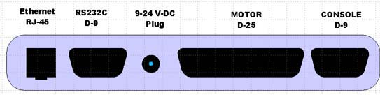
Connections (not by James Burke)
Below is a sketch of the front panel.
I/O Connectors J8 & J10
These connectors are 40 pin so called headers i.e. they are just pins
sticking out of the board. The 40 pin format was selected so that you
can utilise all those flat ribbon IDE cables that are lying around from
decomissioned PCs (I trust you never throw anything away?)
The pins are arrange into 'cluster' as illustrated below.
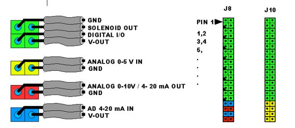
This makes for convenient wiring, just splice the ribbon cable
to threads of two to four wires and connect them. No need to connect
more that one device to one wire.
SPI-Expansion Connector J2
Motor Connector J19
Control Console Connector J23
Ethernet Connector J21
RS232 Connector J22
Power Connector J20
LCD-Display Connector J11
HEX Keypad Connector J14
Errata
J22 - Wrong Gender
This connector (a D9 - RS232C connector) is wired as DTE-equipment, but
the gender of the connector is female, instead of male. So to connect
it to a PC COM port you need a female/male cable with wires 2-3 and 7,8
crossed. This may not be readily available, so you may need to wire it
your self.