Welcome
EazyCNC

jDraft 2.0


PureJavaComm
PIC CDC ACM
Weather
Ten-Buck Furnace
H8S Bootloader
Camera Calibration
Multitouch
Myford VFD
Fun with HC08
bl08

printf II

Java Goes Native
Densitometer
printf

jApp

Igloo

New Furnace

New Furnace
Part II

Linux 101

H8S/gcc
Quickie
Gas Fired Furnace
Down Memory Lane
Exlibris
Wheel Patterns
Glitches
CHIP-8
eDice

Animato

jDraft
JNA Benchmark
Contact Info
This page contains some largish images (click to the images to see the full size) so it may take some time to load on dial up.
Variable Frequency Drive for Myford Super 7
It was a snowy and early March morning, and no one but myself awake when I felt a web page coming up...so join me on this sinister and intriguing tale of the usual cockups and change of plans.
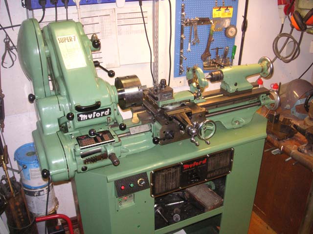
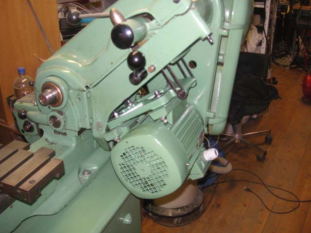
Last summer I managed to acquire a fresh and crisp Myford Super 7 (thanks Mick, once more), which was about 40 years younger than my trusted ML7. The Super 7 came with the original Myford / Brook Crompton Parkinson 550 Watt motor. This is a single phase 2/3 horsepower motor with resilient mounts to reduce unevenness characteristic to single phase drive and a centrifugal clutch (I guess) to ease startup.
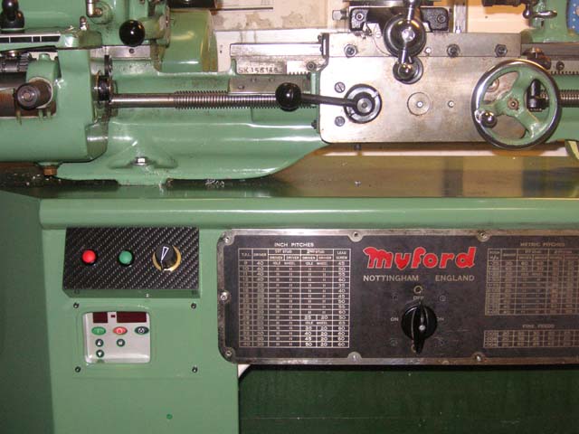
For the reference, this is Myford Super 7, Serial sk 156145 / 1983 and I paid GBP 1850 for it, not including transportation and stand, pictured above after modifications described on this page.
While this is a commonly used motor type with Myfords I felt my new lathe deserved something better. And I had it right there, on my old ML7, an East Germany built three phase 750 Watt (1 hp) VEM motor, with a variable speed drive to match.
So I took the motors off from both lathes and started to figure out how to fit the old motor to the new lathe. Mistake! At this point I realized the pulleys / motors had different diameter axles and I had two lathes none of which was in a condition to turn the bores to fit the axles. And no usable lathe! Oh well, fortunately at work we have a largish prototype shop where turning a bore would be a breeze.
While talking to the foreman of the workshop he inquired if I would be interested in a 1.5 kW (2 hp) VEW motor with variable speed drive that once powered his homemade thread mill. Having used all my allowance on the lathe I was not really in the market for another motor but he persuaded me to get it for a song so how I could have refused?
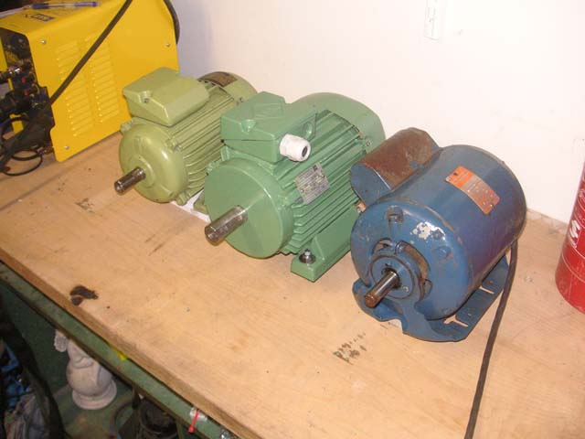
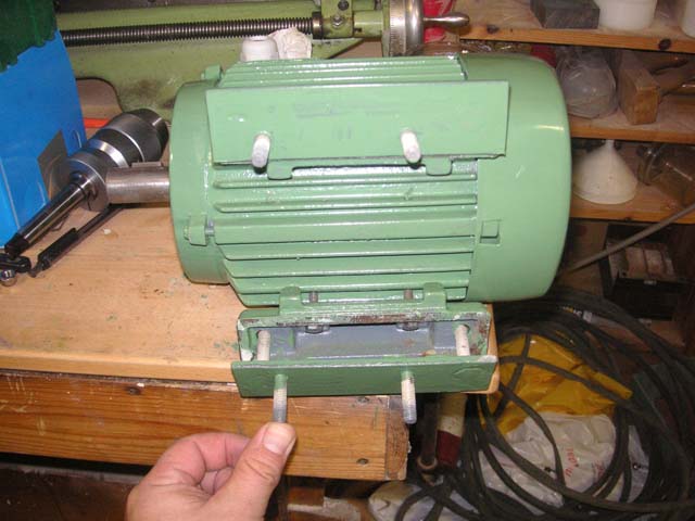
On the picture, from left to right, VEM 750 W, VEM 1.5 kW and 2/3 hp Brook Cropmton. Interestingly the sizes are almost equal and the weight differences is only a few kilo grams.
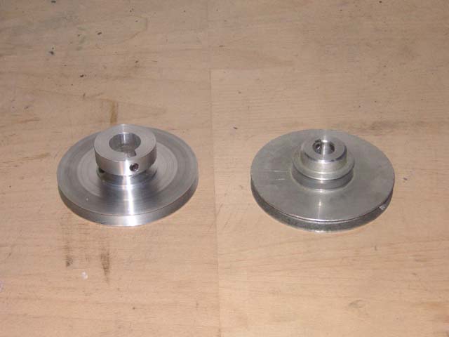 But this new motor brought along another problem, namely that the motor axle on the new motor was even larger than the smaller VEM, so large in fact that the original S7 pulley could no be turned to fit that that axle, the belt groove would have broken into the bore! I had bought this motor and now found it unusable? Fortunately on reflection I realized that the groove on the original pulley was way overkill for the belt and that I could get away with a shallower groove.
The boys at the proto-shop promised to turn me a brand new pulley but they of course needed the drawings for that. I mentioned this to a colleague and before I could say more than half a word a CAD model had been made and the pulley turned with a CNC lathe. At which point I realized I should have said more than half word, as the new pulley had been drafted according to sensible engineering standards, which meant that the smaller half of the pulley was larger than the original Myford design to make room for the axle and keyway. Now, this makes perfect sense, except that with the belt tensioning mechanism in the Super 7 this is a no-go, as the pulley dimensions must be as-designed to allow tensioning to work with a single setting. Oops!
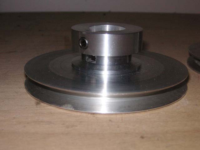 After some consideration we decided that the pulley could be turned down to match the correct size although the groove would brake into the keyway a little. And now it is a beauty, a much better fit to the axle than the original one, I had to use a small rubber mallet to gently persuade it in place. Precision work boys!
Getting a new drive belt was also a saga in itself. All the professional suppliers I contacted said 'oh no you cannot get something that old, nobody uses them anymore'. In the end I found an exact match from local Biltema (belt no 92630, where the 630 is the belt length in millimeters, recorded here for later reference).
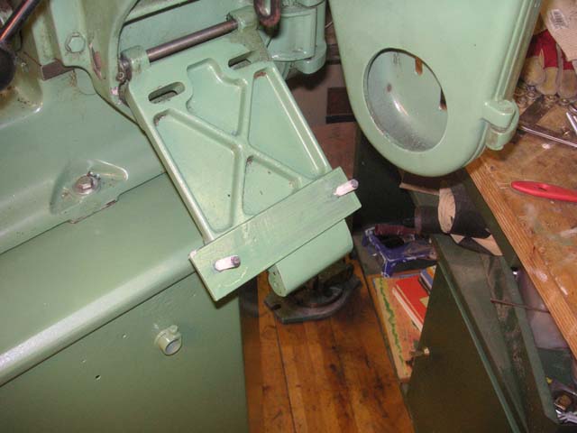
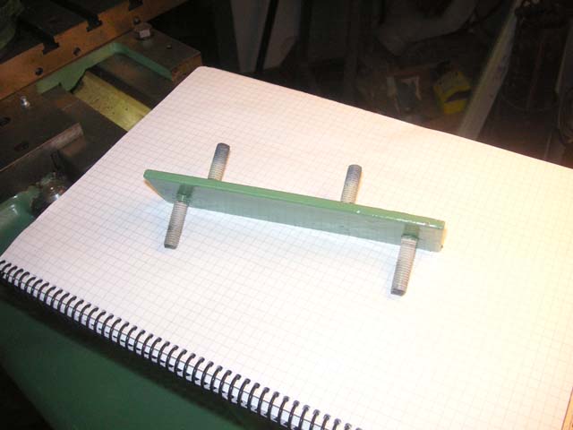
While the pulley adventure had taken its natural course I had been working with adapting the motor as the mount holes on the Myford and motor did not match. Of course not, what do you expect? After rejecting drilling new holes into the Myford (outch) for the motor and contemplating new mount brackets I opted for a simple adapter plate design as shown.
At this point an aesthetic frenzy overtook me and I decided the old lathe stand with its non original color would not do, and that there was no way I would mount a grayish blue motor on my beautifully green Super 7. No sir! So I called up the captain, sorry, wrong song, been listening to Eagles lately, I mean I called up Myford and talked to Malcolm. Yes, he would be happy to supply me with a tin of touch up paint for 15.30 GBP plus some 35 GBP for courier shipping as it cannot be mailed to Finland.
It is always a pleasure to talk to people at Myford but you cannot always say the same for the prices, call me cheapskate and stingy but I call 100 GBP for one liter of paint too dear! In that case they would be happy to supply me with the Myford Green official color code which is RAL 52611 but I would find it difficult to get. And indeed, it was a little more than difficult, how do you spell impossible?
Fortunately the incoming goods inspection department at work has all the gears for colorimetry and was happy to measure the color if I would just bring the lathe over. In the end they let me borrow it over a weekend and I measured the color as:
| SCI 50.92 | -12.40 | 10.69 |
| SCE 46.28 | -14.52 | 12.50 |
When the paint was mixed and the tin opened, amazingly, miraculously, the color was spot on!
So I sanded the lathe stand and over three evenings applied three coats of paint with a brush.
A mistake!
No matter how careful I was the end result was pestered with brush strokes resembling more van Gogh (ok that was mostly palette knife work, but you get the picture, pun intended) than the beautiful finish worth a Super 7.
Restart, reboot, sand it all away and borrow a paint gun from my all around neighbor Pekka. And it really is a pleasure to paint with a paint gun, its fast, its fun and the result looks very professional, don't you think?
| Temalac ab 70 |
| Ts02 230 |
| Ts04 108 |
| Ts05 281 |
| Ts09 209 |
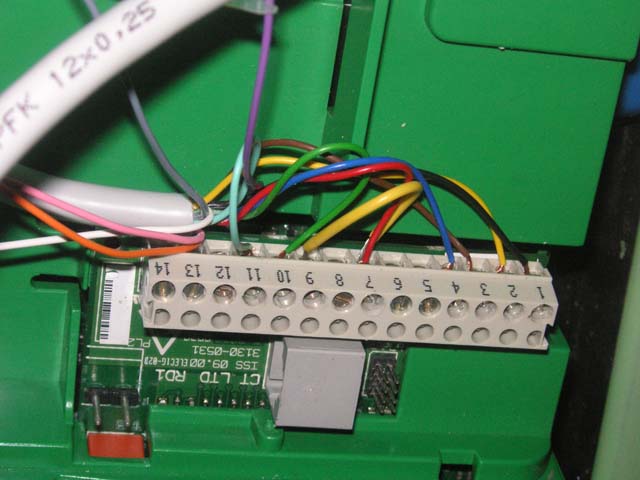
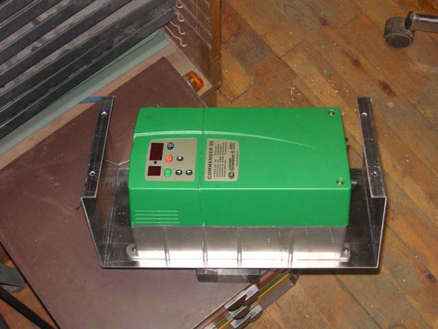 To fit the variable speed drive my plan was to utilize the control panel of the controller as it is. As the controller,Control Technique Commander SE Size 2 , is rather bulky I did not like to bolt it straight onto the lathe stand and besides the swarf would have been sure to enter the controller through the venting holes on top. So I wanted to install it inside the stand. To do that I made support from aluminum that allowed me to bolt the controller from the front although it had mounting holes in the back.
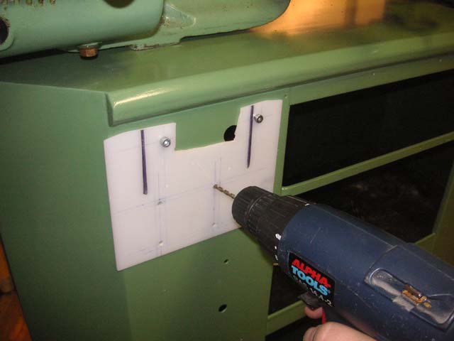
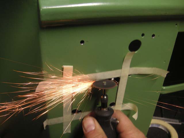
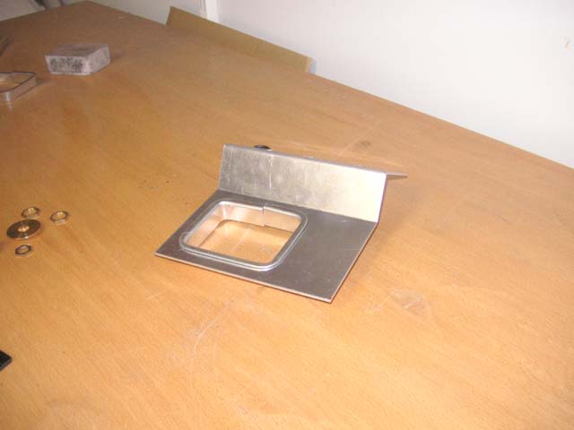
To access the control panel I needed to cut a hole into the front side of the stand. This I did by drilling 10 mm holes in the corners of the cut out and then applied a thin cutting disk with a hand held Dremel to the sides. This was actually pretty simple the only tricky bit was to get it into the right position which was achieved by fitting the aluminum bracket to the controller and drilling mounting holes for the bracket into the stand with the bracket and controller in place and then creating a drilling template using those holes as reference. The ends of the mounting screws for the bracket are inaccessible so instead of nuts I improvised a flat piece of iron into which I tapped with threads for the bolts.
I won't bore you with the details of making a nice little frame around the control panel hole, suffice to say I wasted some hours machining it out of brass, silver-soldering and painting it. This setup served me nicely for some weeks until I wanted install a control knob so that I could easily control the speed instead of using the front panel buttons to program the speed.
My original plan was to just drill a hole for the potentiometer, but on inspection I found out I had left no room for it! So to plan B, surface mount the potentiometer. I turned (at least the lathe was now available) a piece of aluminum to serve as a mounting enclosure and knurled another piece to be used as a knob. Fortunately at this point I tried the setup and found out that, against my preconceptions, the front panel on/off controls are not functional if you program the Commander to take its speed cue from an external potentiometer. Nice one, I don't think.
So trash plan B and the hour wasted on it.
Plan C called for some more careful thinking both mechanically and electrically. The creators of the Commander have had some weirdly limited mind set and left out some perfectly obvious usage scenarios, like using the front panel on/off with an external potentiometer, being able to use the front panel reverse button with external start/stop buttons, being able to use the preset speed inputs without needing a forward signal, being able to use external non-momentary switches for start/stop without losing non voltage release feature, to name a few.
Alas, this was not to be, if only this was an Open Source project I could have changed the software myself!
 So I came up with the set/reset flip flop design based on a relay and some resistors. The Start button momentarily connects voltage to the relay which turns on, connecting voltage continuously onto itself through through the first set of contacts. This will keep the relay turned on until power is cut or the relay coil is short circuited momentarily with the Stop button. The resistor R1 acts to limit the current drawn from the Commander: although the manual says it is okey to short circuit continuously the voltage out at pin 7, it fails to mention that shorting it out will create a fault condition that will require resetting the unit. Nice. Note that the resistor needs to he able to dissipate 24 V / 700 Ohm* 24 V = 0.82 Watts, in case you forget your finger onto the Stop button for extended periods of time, which is why I used two 0.4 W resistors in parallel. The diode D1 is there to protect the Commander power output from the inductive kick from the relay coil.
Some details of the wiring below.
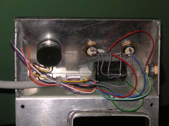
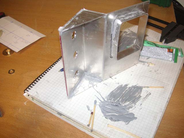
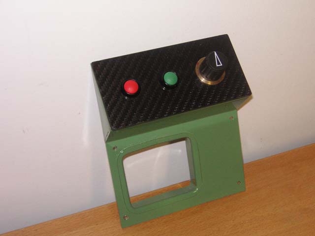
At this point I had to redo the whole front panel construction. The new construction is shown below. Its cut and bent from 1 mm aluminum plate, glued together with 'steel' epoxy from Biltema and painted to match. To give the front panel some class I covered it with carbon fiber plate from an discarded mammography unit compression plate. The relay was simply glued in place and all the connections wired straight onto the pins of the push buttons and the relay. A strain relief clamp for the cord was improvised from aluminum and pop-riveted to protect the connections while it was being fitted.
For a few weeks all was well until it came down to do some thread cutting. At which point I discovered that again my preconceptions were wrong, almost as wrong as the logic of the designers of the Commander: the reverse button on the front panel is just as dead as the on/off buttons, if the external speed control is used! Would it have been too much to ask to have a mode in which the buttons on the front panel had worked with an external speed control? Surely this would have been a useful sales feature.
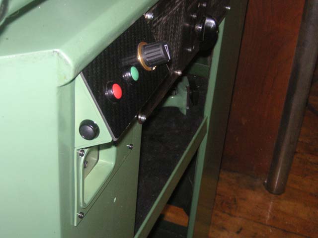 So, off came the panel once more, and I installed a reverse button, fortunately the cable I had used had some extra wires available so I did not have to redo all the wiring. There was no room for it on the nice carbon fiber panel but then again, it sort of makes sense to have it on the side as it is seldom used and it really is not too safe to reverse a Myford with its thread mounted chuck.
There are several ways I could connect the button to the Commander, my first thought being to use it as a 'preset' speed. The manual gives an impression that you can program the controller so that the preset speed is negative, ineffect reversing the rotation, if you just enable the 'sign' from parameter 17. But again I was disappointed with the logic in the Commander.
If you enable the sign, it causes the Commander to ignore parameter 1, the minimum speed setting, which means that instead of your speed potentiometer controlling speed from min to max it makes the lower end to reach all the way to zero speed, which is not what I want and might not be healthy for the motor either, as the cooling would be non existent at those speeds.
And not only that, it is not enough to close the preset switch to make the motor run, you also need to close the run forward or run backward contact.
So I ended up connecting the reverse button to the 'run reverse' contact. This means that, it being a momentary switch, the motor will only reverse as long as the button is pressed, but that is actually very handy when cutting threads which is about the only time you need reverse anyway. This also implies that the reverse speed is the same as the forward speed, which is actually also good as when cutting threads a low speed is required both ways, although I might have preferred to have the reverse speed preset to some programmable value, but that was not to be.
And the finished VFD setup looks quite nice, though I say it meself!
that's all folks,
br Kusti