Welcome
EazyCNC

jDraft 2.0


PureJavaComm
PIC CDC ACM
Weather
Ten-Buck Furnace
H8S Bootloader
Camera Calibration
Multitouch
Myford VFD
Fun with HC08
bl08

printf II

Java Goes Native
Densitometer
printf

jApp

Igloo

New Furnace

New Furnace
Part II

Linux 101

H8S/gcc
Quickie
Gas Fired Furnace
Down Memory Lane
Exlibris
Wheel Patterns
Glitches
CHIP-8
eDice

Animato

jDraft
JNA Benchmark
Contact Info
New Furnace
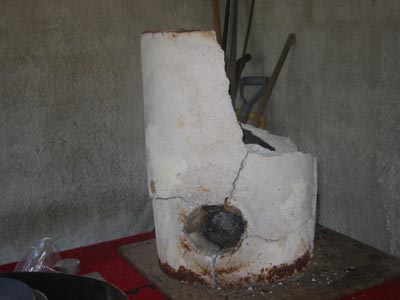 Come spring of -04 and I unearthed the
furnace . Last melt of the previous autumn had manifested
some problems,
the burner tended to backfire and it took a long time to get to melt
temperature. A litle investigation revealed that
the furnace was totally clogged up by iron spills. Originally this
furnace had no bottom (in fact it was a plain tube!) but
I had added a bottom to improve insulation. This was probably futile as
far as heat losses are concerned and stupid
as far as spill are concerned, as there was no hole at the bottom and
the bottom was unremovable. How unremovable it was,
I soon found out.
I tried to hammer (gently as you can with a 4 kg sledge) the bottom
out, and the whole thing fell a part!
Come spring of -04 and I unearthed the
furnace . Last melt of the previous autumn had manifested
some problems,
the burner tended to backfire and it took a long time to get to melt
temperature. A litle investigation revealed that
the furnace was totally clogged up by iron spills. Originally this
furnace had no bottom (in fact it was a plain tube!) but
I had added a bottom to improve insulation. This was probably futile as
far as heat losses are concerned and stupid
as far as spill are concerned, as there was no hole at the bottom and
the bottom was unremovable. How unremovable it was,
I soon found out.
I tried to hammer (gently as you can with a 4 kg sledge) the bottom
out, and the whole thing fell a part!
So, I was in for some furnace construction. Since I had the Gingery Building a Gas Fired Crucible Furnace I thought I'd have a go based on that design. A lot of people have have built it and have not reported problems so I figured it would be ok. On paper the desing seems great and has some nice features. The construction is very economical, it is difficult to see how it could be improved in that respect.
Note that this page is not a DIY instruction, if you want to build one to the Gingery design, go and buy the book. It is worth the dime and we should all engourage people like him to write more on the good stuff.
Having said that the brief discription of the furnace is as follows.
The furnace is made of three parts.
This design has several good points to it: safer access to crucible because , small foot print, compact and economical construction, fast pour/recharge action, simple and inherently rather safe desing.
All features you'll appreciate in a backyard foundry.
The fine print: when above I write safe, it does not mean that the design or activity is safe, it simply means that it is safer than many other designs / practices. Make no mistake, this is dangerous activity. You and you alone will be responsible if you pursue these activities. Do your own risk assement and act accordingly.
 Because I was
planning on casting some roof braces for our conservatory project I
wanted to build a slightly larger furnace that could accomondate
a larger crucible. So I needed to scale up the Gingery desing. This was
a good way to test drive my 2D-CAD program,
jDraft . On the left you can see the scaled up but basically
'standard' Gingery furnace, as captured from my screen. If you are a
jDraft user you can down load the drawing which includes the
dimensioning from here .
If you are not a jDraft user you need to
download jDraft first by visiting the jDraft home page. But you might
want to read the whole story first.
Because I was
planning on casting some roof braces for our conservatory project I
wanted to build a slightly larger furnace that could accomondate
a larger crucible. So I needed to scale up the Gingery desing. This was
a good way to test drive my 2D-CAD program,
jDraft . On the left you can see the scaled up but basically
'standard' Gingery furnace, as captured from my screen. If you are a
jDraft user you can down load the drawing which includes the
dimensioning from here .
If you are not a jDraft user you need to
download jDraft first by visiting the jDraft home page. But you might
want to read the whole story first.
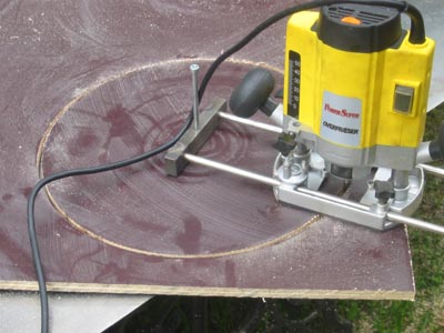 began the construction by cutting two circular
holes to two pieces of plywood with my rooter. Amazing tool, even if
you missposition the cutter so that you are effectively cutting with
the stemp of the cutter only, it just burns away the wood! Mind you
there is a lot of smoke. I also cut two circular discs to be used as
the inside former supports. Actually, one of
these discs was cut so that it was a ring so that I could get my hand
into the inside of the former.
began the construction by cutting two circular
holes to two pieces of plywood with my rooter. Amazing tool, even if
you missposition the cutter so that you are effectively cutting with
the stemp of the cutter only, it just burns away the wood! Mind you
there is a lot of smoke. I also cut two circular discs to be used as
the inside former supports. Actually, one of
these discs was cut so that it was a ring so that I could get my hand
into the inside of the former.
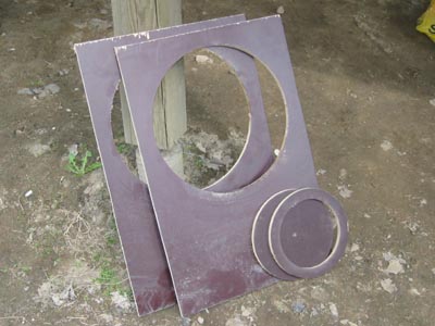 I actually would have needed more of these but
by doing the base, body and lid of the furnace each in turn I was able
to recycle these parts.
I actually would have needed more of these but
by doing the base, body and lid of the furnace each in turn I was able
to recycle these parts.
 The inside former of the furnace body
is made of 1 mm thick mild steep plate. Two small slots were cut into
the inside discs' outer circumference and the end of the inside former
plate was bent to angle so that the end of the plate would fit into the
slot. Then I rolled the plate around the formers. Mild steel was pretty
easy to form
except that I was not able to form a perfect cylinder even with the
help of some heavy pressure from load tying lines.
Finally the former cylinder was secured with some M4 nuts and bolts and
the ever so versatile duct tape.
The inside former of the furnace body
is made of 1 mm thick mild steep plate. Two small slots were cut into
the inside discs' outer circumference and the end of the inside former
plate was bent to angle so that the end of the plate would fit into the
slot. Then I rolled the plate around the formers. Mild steel was pretty
easy to form
except that I was not able to form a perfect cylinder even with the
help of some heavy pressure from load tying lines.
Finally the former cylinder was secured with some M4 nuts and bolts and
the ever so versatile duct tape.
 You can, just about, see the slot in the plywood
ring and the angled plate edge in this picture if you look carefully.
You can, just about, see the slot in the plywood
ring and the angled plate edge in this picture if you look carefully.
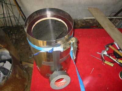
 The outside former for the furnace body I made
from similar steel plate. It was easier to get a good cylinder with
plywood on the outside. Again the former was secured with M4 nuts
and bolts, this time rather many of them about 50 mm appart, as these
bolts are actually the king pins that hold the furnace body
jacket together and prevent it from slipping out. And the body weights
some 65 kg!
The outside former for the furnace body I made
from similar steel plate. It was easier to get a good cylinder with
plywood on the outside. Again the former was secured with M4 nuts
and bolts, this time rather many of them about 50 mm appart, as these
bolts are actually the king pins that hold the furnace body
jacket together and prevent it from slipping out. And the body weights
some 65 kg!
 The two pins that the furnace body rests on are
made of M10 bolts weleded to and re-inforced with some 100 x 100 x 2
mm3 steel plates secured with four M4 nuts and bolts to the furnace
body jacket.
The two pins that the furnace body rests on are
made of M10 bolts weleded to and re-inforced with some 100 x 100 x 2
mm3 steel plates secured with four M4 nuts and bolts to the furnace
body jacket.
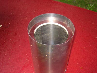
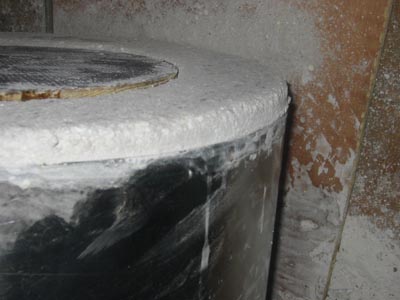
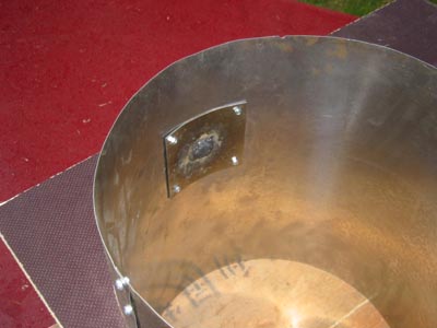 Inside view of furnace body jacket/outside
former. BTW all the outside former plates are left in place ie they are
part of the furnace lining jacket. A full metal jacket?
Inside view of furnace body jacket/outside
former. BTW all the outside former plates are left in place ie they are
part of the furnace lining jacket. A full metal jacket?
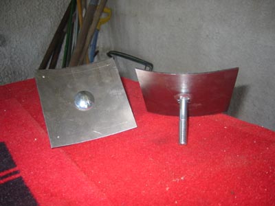
 The burner hole in the base part furnace molds
was
a fun excersize in geometric projection with the jDraft. I printed the
ellipsoid shaped profile of the hole onto a paper that I placed
on top of the steel plate and punched through to mark the hole outline.
The burner hole in the base part furnace molds
was
a fun excersize in geometric projection with the jDraft. I printed the
ellipsoid shaped profile of the hole onto a paper that I placed
on top of the steel plate and punched through to mark the hole outline.
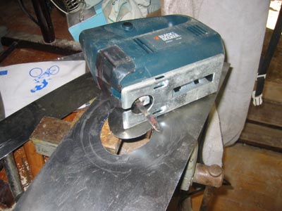 Amazingly the Black&Decker recip saw
just crunched away the metal!
Amazingly the Black&Decker recip saw
just crunched away the metal!
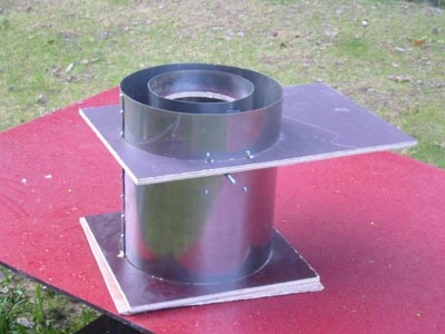
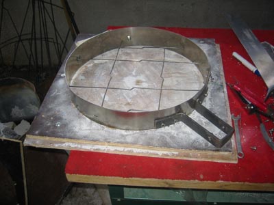
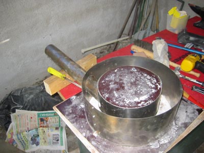 Here the base mold is being tryed out.
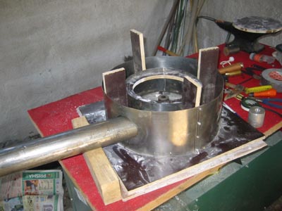 And here the furnace bottom mold is just before
casting the refactory. The four square pieces of plywood were retracted
as I rammed the refactory and the mold filled up.
And here the furnace bottom mold is just before
casting the refactory. The four square pieces of plywood were retracted
as I rammed the refactory and the mold filled up.
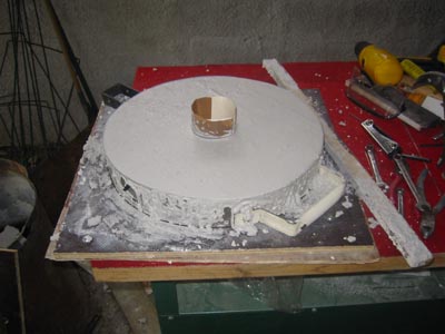
 The lid mold was done pretty much like the
other, I just bolted a piece of angle iron to function as a hinge and
applied some zinc-coated wires across the lid. These are supposed to
attache the frame band to the refactory and also prevent pieces falling
out in case the lid
cracks. BTW, as I said, the base, body and lid were done each in turn
(so not in the sequence show here) so that I could re-use the plywood
formers, like here underneat you can see the same plywood former that
was used to hold the base and the body formers together.
The lid mold was done pretty much like the
other, I just bolted a piece of angle iron to function as a hinge and
applied some zinc-coated wires across the lid. These are supposed to
attache the frame band to the refactory and also prevent pieces falling
out in case the lid
cracks. BTW, as I said, the base, body and lid were done each in turn
(so not in the sequence show here) so that I could re-use the plywood
formers, like here underneat you can see the same plywood former that
was used to hold the base and the body formers together.
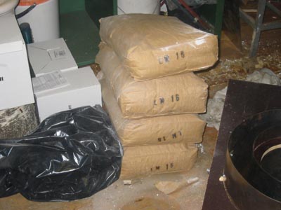 Unlike Gingery I prefer the
commercial variety for my refactory lining. Not because I would not
like to make this myself, I would, but because I feel this is a safety
/ furnace life time issue. An it is not THAT expensive.
Unlike Gingery I prefer the
commercial variety for my refactory lining. Not because I would not
like to make this myself, I would, but because I feel this is a safety
/ furnace life time issue. An it is not THAT expensive.
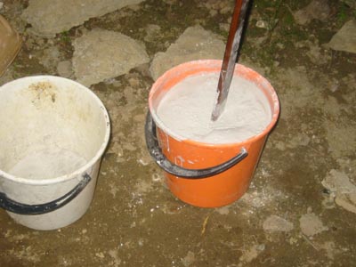 Mixing the stuff is rather hard work and boring.
I used as litle water as possible, the constituency of the mixture was
like porridge made from oat (but not corn ;-) flakes with too litle
water.
Mixing the stuff is rather hard work and boring.
I used as litle water as possible, the constituency of the mixture was
like porridge made from oat (but not corn ;-) flakes with too litle
water.
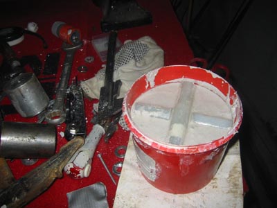
 I just spooned the mixture
into the mold a plastic-cup-full at a time and rammed it hard with a
stick. Too hard as it turned out.
I just spooned the mixture
into the mold a plastic-cup-full at a time and rammed it hard with a
stick. Too hard as it turned out.
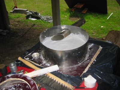
 After about an hour the body
was filled to the rim.
After about an hour the body
was filled to the rim.
 Compared to the body work the lid was a piece
of cake, a pun-cake? (Sorr abot that)
Compared to the body work the lid was a piece
of cake, a pun-cake? (Sorr abot that)
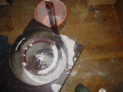
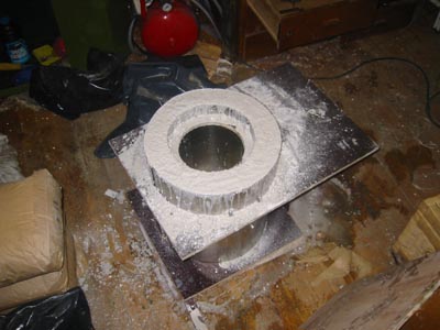
 The base was first filled to the level of the
furnace bottom. The pipe is there, of course, to leave a hole in the
lining for the tangential burner insert. Note that there is a hole in
the bottom to let spilled molten metal to flow out, it is just
difficult to see in this picture as the plug that forms the hole is
covered with white refractory stuff.
The base was first filled to the level of the
furnace bottom. The pipe is there, of course, to leave a hole in the
lining for the tangential burner insert. Note that there is a hole in
the bottom to let spilled molten metal to flow out, it is just
difficult to see in this picture as the plug that forms the hole is
covered with white refractory stuff.
 Then the inside former was inserted and and
centered with the afore mentioned pieces of plywood and the rest of the
lining rammed in while the plywood pieces were retrackted.
Then the inside former was inserted and and
centered with the afore mentioned pieces of plywood and the rest of the
lining rammed in while the plywood pieces were retrackted.
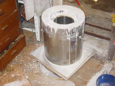 Here is the already hardened body being
stripped down. The top outside former has already been removed, with
help of a saw, as the cylinder turned out slightly concave, which
prevented it from sliding away, so had to cut it free.
Here is the already hardened body being
stripped down. The top outside former has already been removed, with
help of a saw, as the cylinder turned out slightly concave, which
prevented it from sliding away, so had to cut it free.
 All
surplus refactory material was jammed (ha ha) into old strowberry jars
to make flints and small pieces of plastic rod were pushed half way
into the material, as show. These left four cavities that server to
vent out an metal that spills on to the furnace floor.
All
surplus refactory material was jammed (ha ha) into old strowberry jars
to make flints and small pieces of plastic rod were pushed half way
into the material, as show. These left four cavities that server to
vent out an metal that spills on to the furnace floor.
 Like
I said, rammed it too hard! The bottom plywood former shifted and the
bottom of the furnace body was not orthogonal to the cylinder sides. Oh
well, with a diamond disc and an angle crider it took less than ten
minutes to put this right.
Like
I said, rammed it too hard! The bottom plywood former shifted and the
bottom of the furnace body was not orthogonal to the cylinder sides. Oh
well, with a diamond disc and an angle crider it took less than ten
minutes to put this right.
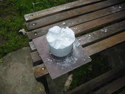 And
here is the flint, still upside down.
And
here is the flint, still upside down.
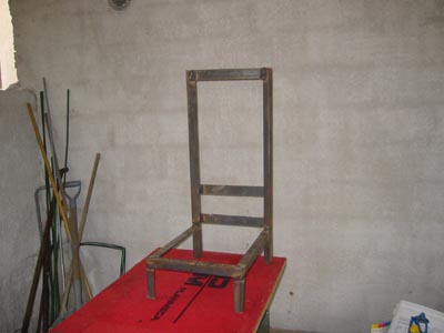 The
frame structure for the furnace was welded together from 30 x 30 x 3 mm
angle iron, except for the vertical columns which are 40 x 40 x 5 mm.
The
frame structure for the furnace was welded together from 30 x 30 x 3 mm
angle iron, except for the vertical columns which are 40 x 40 x 5 mm.
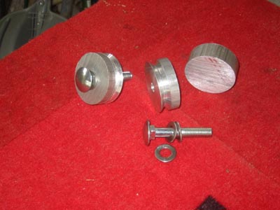 The wheels for the moving lifting mechanism were
cut from a 40 mm dia Al block, turned and fitter with ball bearings.
The wheels for the moving lifting mechanism were
cut from a 40 mm dia Al block, turned and fitter with ball bearings.
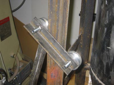 Here
you see the rather small wheel base
inherent in the Gingery design. How inheret, I'll tell you later.
Here
you see the rather small wheel base
inherent in the Gingery design. How inheret, I'll tell you later.
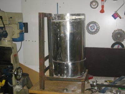 Here all the main parts of the furnace assemble
meet together for the first time. The lift mechanism is still missing.
Here all the main parts of the furnace assemble
meet together for the first time. The lift mechanism is still missing.
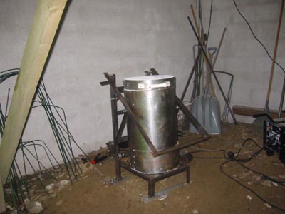 And here the furnace is fully assembled,
ready for action.
And here the furnace is fully assembled,
ready for action.
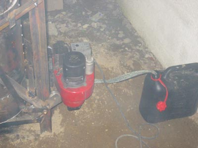
 For the fireworks I decided to try and see if an
oil burner could be utilized. These are readily available as the
companies that sell these are always urging old ladies and gentlemen
that it would be a good time to change that old burner. Usually they
(the burners) are good for
another twenty years, so good second hand burners are easy to obtain.
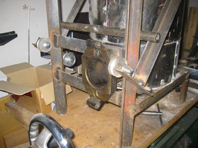
Here you can see the inlet mounted, ready to accept the burner.
For the fireworks I decided to try and see if an
oil burner could be utilized. These are readily available as the
companies that sell these are always urging old ladies and gentlemen
that it would be a good time to change that old burner. Usually they
(the burners) are good for
another twenty years, so good second hand burners are easy to obtain.
Here you can see the inlet mounted, ready to accept the burner.
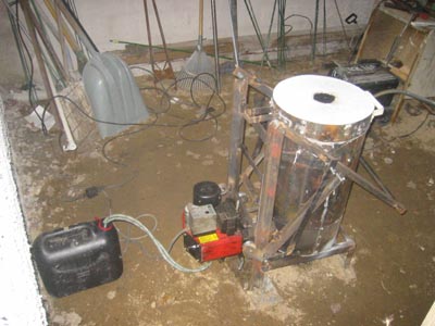 And here the complete furnace and burner
assembly before firing up for the first time.
And here the complete furnace and burner
assembly before firing up for the first time.
 Revers angle view; no I don't watch hockey. As
you can see the burner is a neat package, the atomizing nozzle, high
voltage ingniter, blower, high pressure oil pump, flame guard
electronics all in one easy to mount piece. Just dip the hoses to a can
of fuel and plug it in and with a press of a button it whoooms!
Revers angle view; no I don't watch hockey. As
you can see the burner is a neat package, the atomizing nozzle, high
voltage ingniter, blower, high pressure oil pump, flame guard
electronics all in one easy to mount piece. Just dip the hoses to a can
of fuel and plug it in and with a press of a button it whoooms!
The nice thing about oil firing is that it is rather safe. I
accidentally un-screwed a plug hole while trying to adjust the burner
which was in full blow. The fuel oil (not sure if that is the correct
english term) bursted out and wetted my hands and the sand below before
I could plug it again. But it never caught fire, as it does not burn
readily!
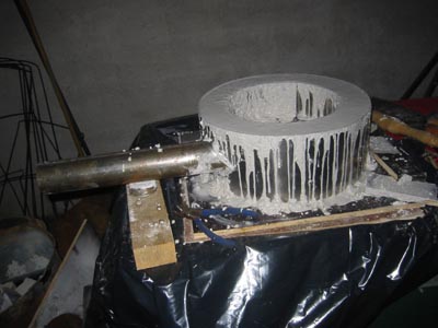
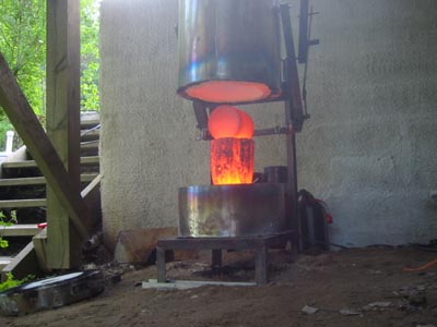 Finally, here is the result of one hour of oil
heating. Bright read orange, but nowhere near what is required for
casting iron. A dissapointment yes, but
not a big deal, I've still got my MarkIV gas burner and that baby is
hot! I do not think this is conclusive, but atleast with this burner it
was not possible to get anything like the blue hot flame (some 1900 deg
C) that any gass burner easily produces.
Finally, here is the result of one hour of oil
heating. Bright read orange, but nowhere near what is required for
casting iron. A dissapointment yes, but
not a big deal, I've still got my MarkIV gas burner and that baby is
hot! I do not think this is conclusive, but atleast with this burner it
was not possible to get anything like the blue hot flame (some 1900 deg
C) that any gass burner easily produces.
All in all I was not totally happy with this new furnace, so, you guessed it, there have been developments since, but I think I'll leave that to another time and page, so tune in for New Furnace - Part II coming soon to a computer screen near you.
cheers Kusti